Right-the-First-Time Welding
Fixing defects demands careful planning and expert execution
Welding repairs often involve higher
stakes than original fabrication. The
pressure is greater, the conditions
are more challenging, and the consequences of
failure are more severe. Once a critical weld is
compromised, the risks increase significantly:
What was critical becomes supercritical, the
margin for error narrows, and the cost of
failure multiplies. A failure in a newly fabricated
pressure vessel might be inconvenient, but a
failure in a repaired pressure vessel already in
service could be catastrophic…
Read the full article here.
Want to optimize your tools?
Check out the BTB MIG Gun Configurator to configure a gun that works with your operation, so you can weld it right the first time.
About the Author
Mostafa Hanafy
Mostafa Hanafy (mostafa.hanafy@bernardtregaskiss.com) is director of strategic marketing and product management at Bernard and Tregaskiss.
Automation for Better Welding
Automation for Better Welding
Technology enhancements optimize and advance automated welding performance.
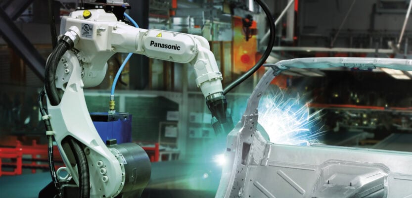
The skilled labor shortage is not a new concern within the welding industry. While efforts are being made to attract new talent, those who join still need ample time to learn and truly refine their skills. Because of shortages and the lengthy on-ramps for newer welders, some operations may still be behind in meeting the demands of their business and struggling with weld quality and consistency issues…
Read the full article here.
Want to optimize your operations?
Check out the Atlas Data Sheet to see how it can improve uptime and minimize training efforts.
To learn more about upgrading your automation efforts visit the Atlas Robotic ThruArm MIG Torch Product Page here.
About the Author
Brad Whipple
Brad Whipple is a senior engineer for Tregaskiss. Email brad.whipple@bernardtregaskiss.com
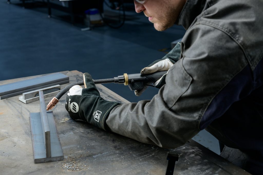
Right Equipment, Better Ergonomics

Right Equipment, Better Ergonomics
A welder that can keep comfortable doing the job is likely to avoid unnecessary strains
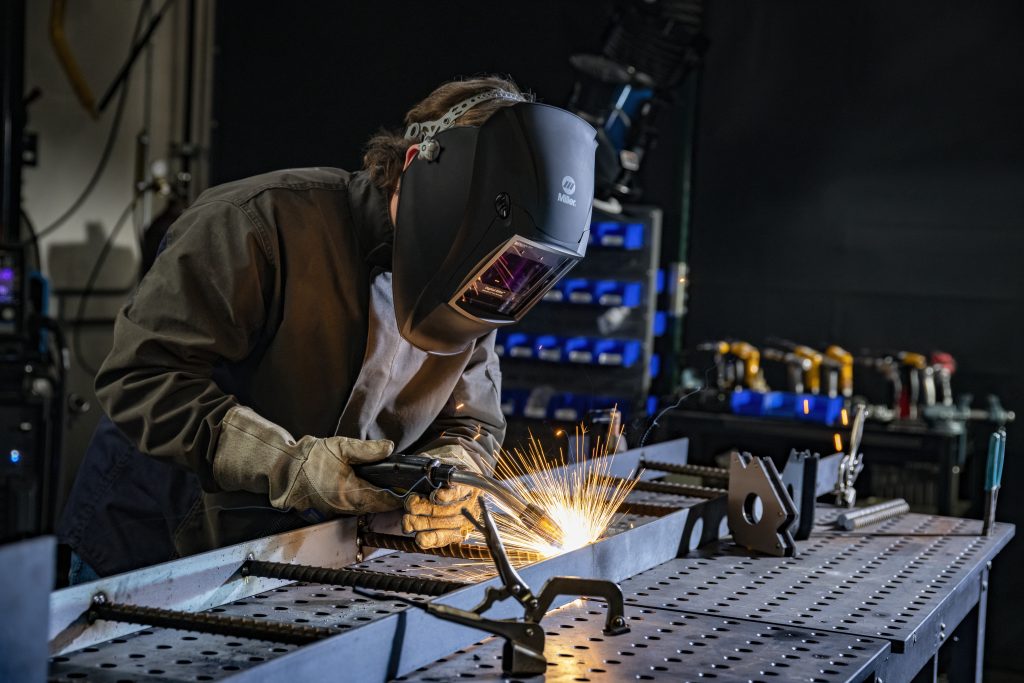
It’s no surprise that as welders reach their 30s, they are not as flexible and limber as they were when they were just starting out in the metal fabricating business. What is surprising is that most companies don’t take that into account, putting these valuable craftsmen at risk of possibly developing sprains and strains that make them unable to work.
These types of ergonomic injuries—pain and damage to muscles, tendons, and ligaments caused by awkward positions and repetitive activities—are real factors in the manufacturing industry. According to the Bureau of Labor Statistics….
Read the full article here.
At Bernard Welding, we place a strong emphasis on welder comfort and ergonomics in every product we release.
By configuring your own MIG gun, you can customize it to fit the way you work—rather than adjusting the way you work to fit the tool. Use our configurator to design a Bernard MIG gun that helps your welders stay comfortable, weld longer, and work more productively; so they can keep delivering quality parts for years to come.
About the Author

Dan Davis
Editor-in-Chief
2135 Point Blvd.
Elgin, IL 60123
815-227-8281
Dan Davis is editor-in-chief of The Fabricator, the industry’s most widely circulated metal fabricating magazine, and its sister publications, The Tube & Pipe Journal and The Welder. He has been with the publications since April 2002.
A Big Win for Clean Air E – Bernard Takes Home a Pro Tool Innovation Award!
A Big Win for Clean Air E – Bernard Takes Home a Pro Tool Innovation Award!
Bernard® Clean Air™ E fume extraction gun has been recognized with a 2025 Pro Tool Innovation Award in the Automotive and Metalworking category, under Welding Guns.
The Pro Tool Innovation Awards are judged by a panel of contractors, trade professionals, and tool experts who evaluate products based on innovation, performance, and value. These awards highlight tools that solve real jobsite challenges and help professionals work more efficiently. Winning products are selected for their ability to improve workflow, boost productivity, and offer new opportunities in the field.
The Automotive and Metalworking category includes tools built for those working with metal or vehicles. It covers everything from welding guns and grinders to inspection tools and accessories. Clean Air E stood out for its ability to deliver cleaner air, better ergonomics, and long-term durability. These key benefits are all critical for demanding industrial environments.
What Makes Clean Air E Different
- Fume Control at the Source – Efficient Extraction
Clean Air E captures up to 95% of weld fumes directly at the arc. This helps protect welders, improves visibility, and supports compliance with health and safety standards. - Comfort That Lasts – Enhanced Ergonomics.
Designed with welders in mind, it features a balanced build, optimized handle, and ball swivel for better control and reduced fatigue during long shifts. - Built to Handle Tough Jobs – Engineered for Endurance.
Its rugged design and long-life consumables reduce downtime and maintenance, keeping operations running smoothly. - Improved Visibility for Better Welds
The gun is engineered to minimize arc obstructions, giving welders a clearer view of the weld puddle for more precise and consistent results.
This award is a reflection of the hard work and collaboration across our team. From product development to launch, everyone played a role in making Clean Air E a success.
You can view the full list of winners at protoolinnovationawards.com.
Interested in the Bernard Clean Air E?
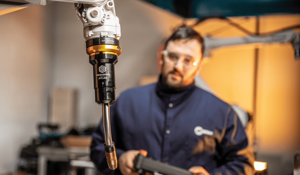
Tregaskiss Redefines Performance With New Atlas™ Robotic ThruArm Air-Cooled MIG Torch
Tregaskiss Redefines Performance With New Atlas™ Robotic ThruArm Air-Cooled MIG Torch
Engineered for precision, built for uptime and designed to hit your mark
BEECHER, Ill./WINDSOR, Ontario (September 4, 2025) — Tregaskiss, a leading innovator in robotic welding solutions, introduces the Atlas™ robotic MIG welding torch — a next-generation, air-cooled ThruArm GMAW torch engineered to deliver unmatched efficiency, repeatable precision and simplified maintenance. Constructed to endure the demands of industrial environments, Atlas helps operators reduce downtime by up to 87% while ensuring consistent, high-quality welds.
Atlas raises the bar in robotic MIG welding and delivers a breakthrough in uptime and weld quality. Its robust construction and streamlined cable routing minimize unplanned downtime and maintenance, while producing high-quality welds across demanding applications.
“We took over three decades of experience and know-how in robotic MIG welding and unleashed our engineers to develop this revolutionary and innovative robotic A/C thru-arm torch,” said Andrew Marchand, director of engineering. “As a result, Atlas sets a new standard in the industry for installation time, TCP repeatability and ease of maintenance.”
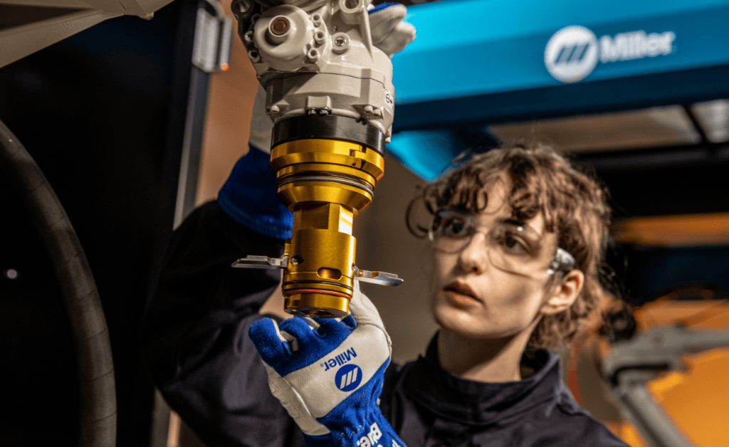
Ideal for operations focused on automotive, heavy equipment and general manufacturing, Atlas sets a new standard with its toughness and accuracy. Key features and benefits include:
- Consistent tool center point (TCP): The keyed stainless steel neck construction provides superior rigidity, long-lasting positional features and increased neck-to-neck repeatability. Additionally, the isolated, separate mechanical and electrical functions, combined with a direct neck-to-cable connection, reduce performance issues.
- Maximized uptime: Tool-less cable change, predictive maintenance indicators and quick-change components reduce unplanned downtime and total service time.
- Designed for durability: Built tough to withstand harsh industrial environments, Atlas protects key components from debris and spatter and extends torch life.
- Streamlined maintenance: Intuitive features like captured fasteners, inspection windows and install confirmation indicators make servicing fast and foolproof.
- Engineered efficiency: The modular, optimized design drives better performance and simplifies training and maintenance.
The Atlas torch will officially debut at FABTECH 2025 this September, where attendees can experience its performance firsthand. Visit booth B20027 from September 8-11 to learn more about Atlas and how it can transform your robotic welding operations.
If you can’t attend the show, visit https://www.bernardtregaskiss.com/product/atlas/ for additional details.
About Tregaskiss
Tregaskiss is a trusted manufacturer of high-quality robotic MIG welding torches and consumables, focused on delivering performance, reliability, and efficiency in automated welding applications. Based in Windsor, Ontario, Tregaskiss designs innovative solutions that offer durability for industrial applications, support system uptime, and reduce maintenance needs in demanding environments. Tregaskiss is a proud brand of Illinois Tool Works Inc. (NYSE: ITW). For more information, visit BernardTregaskiss.com, call 1-855-MIGWELD (1-855-644-9353), or email CS@itwmig.com.
Contact:
Lauren Smith, Hiebing for Bernard/Tregaskiss
phone: +1 6082684408
Contact: Lauren Smith, Hiebing for Bernard/Tregaskiss phone: +1 6082684408 lsmith@hiebing.com
The Hidden Cost of Cutting Corners in Robotic Welding Equipment
The Hidden Cost of Cutting Corners in Robotic Welding Equipment
The global robotic welding market is heating up. This growth is being fueled by a critical mix of factors: a shortage of skilled welders, the rising demand for manufacturing efficiency, and an industry-wide push toward automation across sectors like automotive, aerospace, construction equipment, and general fabrication.
At the center of many robotic welding cells is MIG welding, prized for its speed, adaptability, and suitability for automation. But what often gets overlooked in the race toward automation is this: your system is only as good as the equipment you put into it.
And cutting corners on that equipment? It comes with a price.
Downtime Is Expensive and Often Avoidable
Cheap or underperforming components can quickly turn a high-output robotic welding cell into a bottleneck. From unreliable torches to inconsistent consumables, even minor issues can lead to misaligned welds, excessive spatter, or system stoppages that eat into productivity. Worse yet, these problems are rarely one-offs. Poor-quality components often result in frequent rework, more operator intervention, and additional maintenance all of which erode your ROI over time.
Repeatability and Reliability Shouldn’t Be Optional
Robotic systems rely on repeatable precision. Every weld pass, programmed path and every contact point needs to perform the same, shift after shift. That’s nearly impossible to achieve if your equipment isn’t built to hold tolerances or endure tough environments.
Newer torch designs, like the Tregaskiss® ATLAS™ Robotic ThruArm MIG Torch, have been engineered to deliver consistent, repeatable performance in even the most demanding applications. While not the only solution, products like this are helping manufacturers cut down on downtime and reduce the need for frequent reprogramming or adjustments.
Skilled Labor Is Scarce – Simplicity Matters
With fewer experienced welders and technicians entering the workforce, maintenance routines need to be simplified and, ideally, predictable. Equipment that requires constant tweaking or is difficult to service adds stress and inefficiency to an already stretched workforce.
Modern robotic welding gear is starting to address this. Atlas™ addresses the pain behind predictive maintenance and visual inspection features to take the guesswork out of service intervals. Compatibility with the Tregaskiss Torch Maintenance Module, for instance, allows teams time for maintenance before failure occurs – not after. That kind of visibility leads to fewer unexpected stoppages, fewer errors during maintenance, and more time spent where it counts: welding parts.
The Real Cost Isn’t Just Dollars – It’s Lost Opportunity
In a fast-moving manufacturing environment, the true cost of cutting corners isn’t just found on a balance sheet. It’s in jobs that don’t ship on time. The customers who look elsewhere. The employees are frustrated by constant issues.
Choosing the right robotic welding equipment from the start, even if it comes with a slightly higher price tag is an investment in long-term stability, performance, and productivity. It’s about building a system that works with your team, not against it.

Quality Pays for Itself
As robotic welding continues to expand across industries, the companies that will lead the charge are those who recognize that good equipment isn’t a luxury, it’s a necessity. Whether it’s a rugged torch that stands up to tough environments, or consumables designed for long life and precision, choosing quality upfront prevents pain later.
And in today’s climate of labor shortages, rising expectations, and constant pressure to do more with less, that choice might just be the difference between staying competitive, or falling behind.
Learn more about how Atlas can help save your operation time and money.
GET STARTED.
Improved Flux-Cored Welding for Heavy-Duty Field Use
Improved Flux-Cored Welding for Heavy-Duty Field Use
Understanding operator challenges is what drives innovation in the welding industry. For some, that challenge is outdoor welding, where using shielding gas is not optimal. In these extreme conditions, traditional MIG welding won’t necessarily work. Turning to a different process, such as self-shielded flux-cored welding (FCAW-S), allows for more effective welding in the field. When welding in harsh environments, operators require durable, rugged equipment that can withstand the elements and the nature of the work.
Operators utilizing self-shielded flux-cored welding demand a high level of flexibility and reliability in their equipment, which is why Bernard optimized the IronPro™ self-shielded FCAW gun to be extremely durable when welding in heavy-duty field operations.
Features that enhance flux-cored welding for heavy-duty applications
Operators need a gun that stays cooler in the hand and is lightweight, portable and reliable — handling the rigor of the toughest worksites while improving operator comfort. To improve usability and the overall user experience, IronPro introduces several enhancements to meet those needs and help overcome technical and operational challenges when out in the field.
Specifically, the IronPro 350 has a 350-amp rated output with a 60% duty cycle, making it ideal for operators working in construction, shipbuilding and heavy manufacturing. The design was further updated to include:
- Interchangeable neck options: The IronPro 350 features two rotatable neck options — one that’s 7 inches with a 60-degree bend radius and one that’s 12 inches with a 45-degree bend radius. These allow operators to ergonomically access even the most challenging, out-of-position welds. The neck can be rotated for a trigger-on-top approach, allowing for even more dexterity and customization at the joint.
- Sealed trigger: The trigger is designed to keep the area slag- and spatter-free, reducing maintenance downtime. Being non-metallic, it absorbs less heat, and it’s made with a sealed switch that helps keep out dust and dirt, leading to a longer lifespan.
- Lighter cable: The weight and bulk of higher amperage gun cables can lead to fatigue over extended periods of time. The cable for the 350 is lighter, making it more mobile and user-friendly for a welder on a day-to-day basis.
Incorporating all the updated design features mentioned above, IronPro 450 is also available for higher amperage applications, supporting up to 3/32″ wire size. IronPro 450 has a 450-amp-rated output with a 60% duty cycle.

Additional ways to improve field performance
To keep operators welding in tight positions longer, using AccuLock™ S consumables will increase contact tip life, resulting in fewer tip changes and increased overall performance with fewer points of failure. To further improve field performance, the cable liner incorporates Bernard® E-Z Feed™ technology, ensuring a reliable and smooth feed, minimizing chatter and poor arc characteristics. The superior feeding performance, paired with high-quality consumables, leads to more consistent welds, minimizing rework.
The tip insulator was redesigned to be more durable, withstanding more aggressive weld parameters to keep the electricity from short-circuiting between the tip and neck. Additionally, the insulator transitioned from being a slip-on to a thread-on, allowing it to stay in place better. These design improvements help minimize bridging from spatter and improve operator safety by ensuring the contact tip remains isolated to allow current to flow correctly through the wire to the weld puddle. Operators can choose between composite tip insulators, for increased joint access, or armored tip insulators, which are well-suited for higher amperage applications. These options allow operators to better customize their IronPro to suit the needs of their applications.

When welding heavy-duty applications in the field, operators need power, durability and consistency. The IronPro 350 offers improvements that exceed those demands. Welders can elevate their welding performance — and experience the productivity and quality benefits self-shielded flux-cored welding offers.
4 Reasons Genuine Consumables Lead to Better MIG Welds

4 Reasons Genuine Consumables Lead to Better MIG Welds
Welders must be able to rely on every aspect of their equipment, and consumables are an integral component of a high-quality weld. When you notice an uptick in downtime and consumables consumption, it’s time to take a deeper look at what the culprit could be. An easy place to start is by looking at the quality of the consumables you’re using. Lower-quality consumables can lead to major expenses in the long run — as seen in lost production, weld rework and the cost of constant replacements.
Original equipment manufacturer (OEM) consumables are the right choice for improved operations and consistent, high-quality welds. Below are four reasons you should consider investing in genuine consumables over lower-quality options.

- Consumable quality affects your performance
Even the best MIG guns or the most highly trained operators cannot offset the impact of poorly made consumables on performance. OEM consumables are manufactured using high-quality materials, which helps deliver the arc stability needed to create smooth, even welds with minimal defects. In addition to helping improve weld integrity and facilitating more durable weld joints, genuine consumables also help prevent excessive spatter and minimize post-weld cleanup.
Because OEM consumables are manufactured for reliability, they have consistent diameters and surface conditions that ensure smoother feeding through the gun. By contrast, non-genuine consumables are often made from low-quality materials and may not consistently meet key manufacturing specifications.
2. OEM consumables are expertly designed to be reliable
Genuine consumables are backed by research, technology and expertise, having been produced to ensure the material composition and mechanical properties are consistent and reliable. Keeping those details at the forefront makes for stable arcs, high-quality welds, fewer points of failure and simplified maintenance. Their ease of use can even help to reduce welder training times and shorten your troubleshooting list if problems do arise.

Copycat manufacturers are also less likely to submit their consumables to the rigorous testing and quality assurance processes that OEMs follow.
AccuLock ™ consumables have been designed to flawlessly integrate into Bernard® semi-automatic and Tregaskiss® fixed automatic and robotic MIG welding guns and to address welders’ most common pain points.
For semi-automatic MIG welding applications, the AccuLock™ S consumables system paired with front load E-Z Feed™ liners reduces liner trim length errors and erratic wire feeding while simultaneously increasing contact tip life. The front load liners are locked and concentrically aligned to both the contact tip and power pin. This eliminates misalignment and provides a flawless wire feed path, ensuring uninterrupted delivery of the wire to the weld puddle. As a result, operators have fewer burnbacks, bird nests and erratic arcs.
The AccuLock R consumables system is available for robotic or fixed automatic MIG welding applications. With these consumables, operators have the opportunity to realize significant improvements, like increasing contact tip life span and decreasing issues with contact tip cross-threading.
For operations constantly managing complex or costly consumables inventories, AccuLock S and AccuLock R consumables systems share a common contact tip — making for simplified part inventory across mixed fleets of semi-automatic and automated welding applications. Operations who are looking to get more life out of their consumables but aren’t using Bernard or Tregaskiss guns can purchase the conversion series consumables to still experience the benefits of a high-quality system.
3. Using low-quality products limits your manufacturer’s ability to help
A good OEM is invested not only in the performance of its products but also in the overall user experience, which extends to customer service. Reputable OEMs usually have expert technical support teams that help with troubleshooting and provide solutions if something goes wrong. They can also share product tips and offer advice, like how to make your MIG gun consumables last longer.

However, if you’re using nongenuine consumables and parts, technical support teams are unable to offer such assistance. Often, if an issue arises involving lower-quality parts, it will be essential to order genuine parts and wait for them to arrive to see if the issue still occurs before the OEM team can offer support. Using genuine parts from the get-go means you can get expert advice right away — or avoid issues altogether.
4. OEM products can have a longer life
Because OEMs are making greater investments in materials, design and testing, that means OEM consumables usually cost more than low-quality consumables. But, as the saying goes, you get what you pay for. Consumables are probably not your biggest cost — labor is. So any money you save by using cheaply made consumables could be offset by the extra labor required to frequently change tips, troubleshoot equipment failure or rework a faulty weld. Those looking for superior performance and longevity find that OEM options can equate to more arc-on time — and more products out the door.
AccuLock contact tips are designed so that 60% of the tip is buried within the diffuser for less exposure to the heat of the arc and more cooling from shielding gas. This gives the tip a life that can be two to three times longer than other tips.
All told, because genuine consumables are designed specifically for your MIG welding gun, they can last longer, be more reliable and deliver higher-quality welds — ultimately enhancing the operator experience and your welding operation’s bottom line.
Introducing The Bernard® Clean Air E™

Introducing The Bernard® Clean Air E™
Welding professionals face daily challenges in keeping their work environment clean and safe. With strict weld fume regulations, effective fume control is more important than ever. The Bernard® Clean Air E™ fume extraction MIG gun helps by capturing welding fumes directly at the source without sacrificing performance.
Why Source Capture Matters
Capturing weld fume as close to the point of generation as possible, also known as source capture, is one of the most effective ways to reduce exposure. Unlike general ventilation or ambient air systems that dilute fumes, source capture methods like fume extraction guns immediately remove hazardous particles, helping improve air quality for operators and surrounding workers.
The Clean Air E™ captures up to 95% of fume at the source. The gun is built with adjustable extraction control through interchangeable shroud lengths and a slider allowing operators to fine-tune suction levels without affecting shielding gas coverage. This balance is critical for maintaining weld quality while maximizing fume capture.
Key Benefits of the Clean Air E™
Efficient Extraction
By removing up to 95% of fumes directly at the arc, the Clean Air E™ helps reduce exposure risks and contributes to a cleaner workspace.
Enhanced Ergonomics
With a lightweight handle design, the Clean Air E™ allows you to weld longer without fatigue. The ball swivel at the rear of the handle makes maneuvering easier, even in difficult positions.
Engineered for Endurance
This fume gun is built to withstand the toughest working environments. Made from durable, tested materials, it features a robust and straightforward design for easy maintenance.
Designed for Demanding Applications
Ideal for high-amperage and high-deposition rate applications, the Clean Air E™ is well-suited for industries such as: Shipbuilding, Heavy equipment manufacturing, General fabrication and manufacturing
Ergonomic and Easy to Use
Unlike bulky ventilation systems, fume extraction guns like the Clean Air E™ seamlessly integrate into a welder’s workflow. With a lightweight, ergonomic design and a user-friendly adjustment slider on the guns handle, it operates much like a standard MIG gun while providing the added benefit of fume extraction.

Customizable
We know every welder has their own preference when it comes to welding style. That’s why we designed two trigger options—a button and a lever, plus an extended lever for added comfort. We also made the shrouds interchangeable, offering three lengths to optimize either weld visibility or fume extraction, depending on your application.
A Smarter Step Toward Safer Welding
No single solution eliminates all welding fume exposure, but using a fume extraction gun alongside a compatible extraction unit like the Miller® Filtair®215 can significantly improve a workplace environment. The Bernard® Clean Air E™ provides a practical, effective way to prioritize welder safety and performance.

It starts at the source™
For Immediate Release BEECHER, Ill./WINDSOR, Ontario (March 20, 2025) — Bernard announced the release of the new Clean Air E™ fume extraction MIG gun, the newest high-efficiency fume extraction gun in the brand’s lineup. Crafted for efficient extraction, enhanced ergonomics and engineered endurance, this gun sets a new standard in MIG welding fume capture technology. With an ongoing priority to ensure safer, cleaner work environments for operators coupled with heightened fume standards being implemented across the country, Bernard saw an opportunity to evolve the standard fume extraction gun to maximize its efficiency and usability. Bernard took customer and welder feedback and designed a product that would be the most impactful for welders in a next-generation fume extraction gun. The team applied that feedback throughout the research and development process until it resulted in the Clean Air E™, which offers solutions to common operator pain points, including: · Efficient extraction: The Clean Air E™ achieves up to 95% fume capture right at the source, which improves air quality in the workspace and reduces OSHA-related risks. · Enhanced ergonomics: The ergonomic design reduces strain and fatigue on welders, which allows them to focus on precision and quality for extended use. · Engineered for endurance: The Clean Air E™ features durable components and long-life consumables, which reduces downtime and maintenance costs, delivering a lower cost of total ownership. “When it comes to welding, operators seek the trifecta in their gun: ergonomics, extraction performance and ease of maintenance,” said Jerome Parker, product manager, Bernard. “The Clean Air E™ was designed alongside actual users to ensure we arrived at a solution that redefined traditional fume capture guns for the modern welder, enhancing both their operator experience and their weld environment.” On the gun itself, the Clean Air E™ offers enhanced features for easier and more efficient use: · Improved weld access: Three nozzle shroud lengths allow operators to balance fume capture with weld access and improved visibility of the weldment. · Instant flow adjustment: The new flow control slide on the back of the handle enables welders to easily reduce airflow by up to 10 cfm to help overcome porosity issues. · Upgraded handle comfort: Two handle styles are available to suit different grip styles and hand sizes, with internals contoured to enhance airflow and fume capture. The lever trigger can also be mounted on top for additional comfort. · Increased flexibility: A durable, lightweight aluminum ball swivel at the end of the handle provides 15 degrees of extra flex in any direction for additional improved ergonomics. · Maximized airflow: A new Y-connector offers contoured internals that maximize airflow, with a vacuum outlet that is compatible with any fume extraction unit. For a premium fume extraction pairing, operators have the option to connect the Clean Air E™ to the Miller® FILTAIR® 215. Learn more about how the Clean Air E™ can deliver safety, performance and comfort for welders at https://www.startsatthesource.com/ About Bernard Bernard, a leading manufacturer of premium semi-automatic MIG welding guns and consumables, is dedicated to enhancing welding productivity and performance. Headquartered in Beecher, Illinois, Bernard is known for innovative solutions that prioritize operator comfort, ease of maintenance, and exceptional durability. Bernard is a proud brand of Illinois Tool Works Inc. (NYSE: ITW). For more information, visit BernardTregaskiss.com, call 1-855-MIGWELD (1-855-644-9353), email CS@itwmig.com. Contact: Lauren Smith, Hiebing for Bernard/Tregaskiss phone: +1 6082684408 lsmith@hiebing.com The Occupational Safety and Health Administration (OSHA) and other safety regulatory bodies set the allowable exposure limits for weld fumes and other particulates, including hexavalent chromium, with the aim of protecting employees against potential health hazards in the workplace. Providing welding operators with proper ventilation during the welding process is an important step companies can take to help meet the standards — and to help provide a safe and comfortable work environment. Companies may opt to invest in centralized fume extraction systems, which are designed to protect the entire shop area. These systems involve the installation of new ductwork and fans to remove fumes and are highly effective, but they are also more expensive than other options. A viable alternative for some companies is a fume extraction gun used in conjunction with a fume extraction device or localized filtration system. Fume extraction guns are available in a variety of amperages (typically 300 to 600), cable styles and handle designs. As with any welding equipment, they have their best applications, advantages and limitations, as well as recommended techniques for achieving the best results. Fume extraction guns operate by capturing the fume generated by the welding process right at the source, over and around the weld pool. The weld fumes removed by these guns are composed of a combination of the filler metal and base material. Various manufacturers have proprietary means of constructing guns to conduct this action, but at a basic level they all operate similarly: by mass flow, or the movement of material. A vacuum chamber suctions the fumes through the handle of the gun, into the gun’s hose and through to a port on the filtration system (sometimes informally referred to as a vacuum box). Typically, fume extraction guns are larger than regular welding guns, and include the vacuum and hose that are necessary to extract the fumes. Some manufacturers offer fume extraction guns with a vacuum hose swivel on the rear of the handle to make them easier to maneuver. Also, design advancements have minimized the handle weight and size to make the guns as light as possible for operator comfort, while still offering consistent fume extraction benefits. The Bernard® Clean Air E™ fume extraction gun is designed to efficiently capture welding fumes at the source, helping to create a cleaner work environment. This gun is particularly well-suited for applications using solid welding wire and for operations in confined spaces, where fume extraction directly in the welding operator’s breathing zone is essential. Industries that frequently benefit from this technology include shipbuilding, heavy equipment manufacturing, and general fabrication, especially when working with mild or carbon steel. Additionally, for applications in petrochemical industries or those involving stainless steel welding, where higher levels of hexavalent chromium are present, the Clean Air E™ gun provides an effective solution for improving air quality. Designed for high-amperage and high-deposition rate applications, this gun performs best in flat and horizontal welding positions, where it can effectively capture rising fume particles. While fume extraction in out-of-position welding can be more challenging due to the natural rise of fumes, proper technique and positioning can help maximize effectiveness. The Clean Air E™ fume extraction gun operates similarly to a standard MIG gun, making it easy for welding operators to adapt to. To achieve the best results, consider these best practices: By integrating the Bernard® Clean Air™ E fume extraction gun into your welding operations, you can enhance fume control while maintaining welding quality and efficiency. Fume extraction guns operate by capturing the fume generated by the welding process right at the source, over and around the weld pool. As with any piece of welding equipment, fume extraction guns benefit from preventive maintenance. Flux-cored wire allows vacuum adjustment Because flux-cored wire produces a slag, it generates more weld fume. However, one benefit of using self-shielded flux-cored wire, for example, is it allows the ability to increase the vacuum level of the gun. Welding operators can close off all the vents and utilize the long shroud. This action maximizes the vacuum at the front end of the gun without concern for disturbing the shielding gas, since there is none generates with self-shielded flux-cored wire. When using gas-shielded flux-cored wire, a 0 to 15-degree angle will help maximize fume collection. Pause at the end At the end of the weld, welding operators can pause for 10 to 15 seconds, holding the fume extraction gun in place without depositing weld metal. This action allows the gun to capture residual fumes as the weld bead is cooling. Wire type determines stickout The contact tip to work distance can be longer — about 1/2 inch to 3/4 inch — when welding with flux-cored wire and a fume extraction gun. With solid wire, welding operators should try to keep the stickout to 1/2 inch or less to maximize fume capture. These lengths are comparable to the stickout lengths used with standard MIG guns. Experiment with the air control regulator Some guns, like the Clean Air E™, incorporate a slider or toggle mechanism conveniently located on the gun handle, while others integrate this function internally. This adjustability is essential for balancing fume extraction with shielding gas coverage. Too much suction can disrupt the protective gas flow, leading to weld defects like porosity, while too little may not effectively capture harmful fumes. By using the built-in adjustment feature, operators can increase or decrease suction as needed to maintain optimal fume control while ensuring proper weld protection. Finding the right balance may require some trial and error. To optimize performance, welding operators should test the air control setting on scrap material before welding on a final product. This ensures that fume extraction is maximized without negatively affecting weld quality. With the Clean Air E™ and other adjustable fume extraction guns, operators have greater control over their work environment—helping to improve air quality while maintaining welding efficiency. As with any piece of welding equipment, fume extraction guns benefit from preventive maintenance. Caring for them is similar to caring for a standard MIG gun. Also note that using flux-cored wire with these guns requires more frequent gun maintenance than solid wire because of the slag and fumes it generates. Regular maintenance is important to help prevent a clog or spatter buildup, which can limit the fume capture rate. Inspecting and maintaining the front end of the gun is key to optimizing fume extraction. Frequently inspect the nozzle and contact tip for signs of spatter buildup, which along with blocking the fume extraction can also obstruct shielding gas flow and cause weld defects. Spatter buildup also can cause consumables to fail prematurely. Replace the consumables if spatter buildup appears, or clean them according to the manufacturer’s recommendations. Also, inspect the vacuum hose regularly for damage such as cuts or kinks, which can lead to loss of suction. Replace a damaged vacuum hose as necessary. Regarding consumables, using the manufacturer’s recommended consumables package with a fume extraction gun helps optimize performance, as the guns are engineered to get the best results with specific consumables. When in doubt about maintenance or any other aspect of using a fume extraction gun, consider working with a trusted welding distributor, certified industrial hygienist and/or the gun manufacturer to address any questions or concerns. In combination with many other variables in the welding operation — wire selection, specific transfer methods and welding processes, welding operator technique, and base material selection — fume extraction guns can help companies maintain compliance with safety regulations and create a cleaner, more comfortable welding environment. Proper use and maintenance of the equipment is important to get optimal results.
New industry standards from the Occupational Safety and Health Administration (OSHA) are protecting employees against potential health hazards in the workplace. These regulations, which dictate allowable exposure limits of welding fumes and other particulates (including hexavalent chromium), have led many companies to invest in fume extraction equipment. An increased desire to maintain optimal welding operator safety and to attract new skilled welding operators to the field is also a consideration in investing in this equipment — companies want to create the most comfortable and healthy work environment possible. The Clean Air E™ MIG fume extraction gun, as shown here, operates by capturing the fume generated by the welding process right at the source, over and around the weld pool. With interchangeable shroud options to help customize your extraction for your application. Some companies may opt for centralized fume extraction systems, which are designed to protect the entire shop area. These systems involve the installation of new ductwork and can be a costly investment for capturing fume particulate in the air. Fume extraction guns are available in a variety of amperages, cable styles and handle designs. As with any welding equipment, they have their advantages and limitations, best applications, maintenance requirements and more. In combination with many other variables in the welding operation; welding wire selection, specific transfer methods and welding processes, welding operator behavior and base material selection — fume extraction guns can help companies maintain compliance with safety regulations and create a cleaner, more comfortable welding environment. Fume extraction guns operate by capturing the fume generated by the welding process right at the source, over and around the weld pool. Various manufacturers have proprietary means of constructing guns to conduct this action, but at a basic level they all operate similarly: by mass flow, or the movement of material. This movement occurs by way of a vacuum chamber that suctions the fumes through the handle of the gun, into the gun’s hose through to a port on the filtration system (sometimes informally referred to as a vacuum box) like the Miller FILTAIR® 215 High-Vacuum Fume Extractor. The welding fumes that these guns remove are composed of a combination of the filler metal and base material. Some fume extraction guns feature adjustable extraction control regulators at the front of the gun handle, which allow welding operators to increase suction as needed (without affecting shielding gas coverage), while others provide this function internally. Regardless of the manner, the ability to balance between the downward flow of shielding gas and the upward flow of the suctioned air is critical. The fume extraction gun needs to provide the appropriate amount of shielding gas to protect the weld from defects such as porosity, without sacrificing the ability to suction fumes efficiently enough to protect the welding operator. The balance allows the weld pool time to react and solidify, and gives the fume particles time to decelerate so they are easier to extract. Typically, fume extraction guns are larger than regular welding guns and tend to be bulky due to the vacuum and hose necessary to extract the fumes. For that reason, some manufacturers create fume extraction guns with a vacuum hose swivel on the rear of the handle to make them easier to maneuver. Manufacturers have also, since fume extraction guns were first introduced (in the late 1960s and early 1970s), found ways to engineer internal components to minimize the handle weight in order to reduce operator fatigue. Fume extraction guns are well-suited for applications using solid welding wire and those in confined spaces. These include, but are not limited to applications in the shipbuilding and heavy equipment manufacturing industries, as well as general manufacturing and fabrication. They are also ideal for welding on stainless steel applications, as this material generates greater levels of hexavalent chromium, and on mild and carbon steel applications. The guns also work well on high amperage and high deposition rate applications and are available, typically, in 300 to 600 amp ranges. Fume extraction guns attach to a localized filtration system, as shown here. Fume removal occurs by way of a vacuum chamber in the fume extraction gun that suctions the fumes through the handle of the gun, into the gun’s hose through to a port on the filtration system. For the best results, fume extraction guns should be used for in-position welding, such as on flat butt welds. In this position, they can most effectively capture fume particles as they rise from the weld pool. In out-of-position welds, the energy of the fume particles causes them to rise at a high rate, making it more difficult for the fume extraction gun to draw them downward and through the vacuum hose. One distinct advantage to fume extraction guns is that they remove the fumes at the source. This will minimize the amount that enters the welding operator’s immediate breathing zone. As with any piece of welding equipment, fume extraction guns benefit from preventive maintenance. Caring for them is similar to caring for a standard GMAW gun. Regularly check for tight connections throughout the length of the fume extraction gun to ensure good electrical flow. Minimizing electrical resistance helps ensure consistent weld quality and prevent premature failure of the front-end consumables — contact tip, nozzle and diffuser. Frequently inspect the nozzle and contact tip for signs of spatter build-up, too, as such build-up can obstruct shielding gas flow and cause weld defects that ultimately will need to be reworked. Spatter build-up can also cause consumables to fail prematurely. Replace the consumables if spatter build-up appears or clean them according to the manufacturer’s recommendation. In some cases the shroud that surrounds the nozzle may also have to be replaced or cleaned free of spatter. To ensure optimal fume extraction capabilities, inspect the vacuum hose regularly for damage, including cuts or kinks that could lead to loss of suction. Replace a damaged vacuum hose as necessary and dispose of it according to the manufacturer’s and/or an industrial hygienist’s directions. Visually inspect the handle for cracks or missing screws, and also check that the gun’s trigger is not sticking or otherwise malfunctioning. Replace or repair these components as necessary. Finally, maintenance on the liner is also important. As with the vacuum hose, use compressed air to clear out any potential blockages during welding wire changeovers or when removing the wire from the gun. Spending an extra few minutes clearing out any debris from the liner can save considerably more time than troubleshooting the weld defects and equipment problems that can result from blockages. Also, track the amount of time that it takes for a liner to wear during the course of the welding operation. Replace the liner prior to that in the future to prevent downtime for replacement during shifts or problems with wire feeding or quality. When in doubt about maintenance or any other aspect of using a fume extraction gun, consider working with a trusted welding distributor, certified industrial hygienist and/or the fume extraction gun manufacturer to address any questions or concerns. Proper use of this equipment can help provide optimal results, and improve the safety and comfort of the welding environment. Having the right equipment in the welding operation is important — and making sure it works when it’s needed is even more so. Welding gun failures cause lost time and money, not to mention frustration. Like with many other aspects of the welding operation, the most important way to prevent this problem is education. Understanding how to properly choose, set up and use a MIG gun can help optimize results and eliminate many of the problems that lead to gun failure. Learn about five common reasons MIG guns fail and how to prevent them. The rating on a MIG gun reflects the temperatures above which the handle or cable becomes uncomfortably warm. These ratings do not identify the point at which the welding gun risks damage or failure. Much of the difference lies in the duty cycle of the gun. Because manufacturers can rate their guns at 100%, 60% or 35% duty cycles, there can be significant variances when comparing manufacturer’s products. Duty cycle is the amount of arc-on time within a 10-minute period. One manufacturer may produce a 400-amp GMAW gun that is capable of welding at 100% duty cycle, while another manufactures the same amperage gun that can weld at only 60% duty cycle. The first gun would be able to weld comfortably at full amperage for a 10-minute time frame, whereas the latter would only be able to weld comfortably for 6 minutes before experiencing higher handle temperatures. Choose a gun with an amperage rating that matches the necessary duty cycle required and the length of time that the operator will be welding. It’s also important to consider the materials and filler metal wire that will be used. The gun should be able to carry enough power to melt the filler metal wire cleanly and consistently. Improper system setup can increase the risk of welding gun failure. It’s important to pay attention to not only all consumable connections within the gun, but also all connections in the entire weld circuit to optimize performance. Proper grounding helps ensure the operator isn’t sending too much power to a restricted window for the power to travel through. Loose or improper ground connections can increase resistance in the electrical circuit. Be sure to put the ground as close to the workpiece as possible — ideally on the table that holds the workpiece. This helps provide the cleanest circuit structure for the power to travel where it needs to go. It’s also important to place the ground on clean surfaces so there is metal-to-metal contact; do not use a painted or dirty surface. A clean surface gives the power an easy path to travel rather than create obstructions that create resistance — which increases heat. Consumable connections play an important role in gun performance. Consumables should be tightly secured to the gun, and all threaded connections should also be secure. It’s especially important to check and tighten all connections after a gun has been serviced or repaired. A loose contact tip or gun neck is an invitation for gun failure at that spot. When connections aren’t tight, heat and resistance can build up. Also, be sure any trigger connect being used is working properly and provides constant power. Cables can be easily damaged in the shop or manufacturing environment; for example, by heavy equipment or improper storage. Any damage to the power cable should be repaired as quickly as possible. Inspect the cable for any cuts or damage; no copper should be exposed in any part of the cable. An exposed line of power in the weld system will try to jump the arc if it touches anything metallic outside of the system. This can result in a wider system failure and a possible safety concern. Re-terminate the gun and make the cable shorter if necessary, removing any cable sections that have nicks or cuts. Also be sure the power cable is the proper size for the power that the feeder is supplying to the weld gun. An oversized power cable adds unnecessary weight, while an undersized cable causes heat buildup. The manufacturing environment can be harsh for tools and equipment. Take care of tools and equipment to help extend their useful life. Skipping maintenance or treating tools poorly can result in failure and reduced life. If the welding gun is connected to a boom arm above the weld cell, make sure there are no areas where the gun or cable can be pinched or damaged. Set up the cell so there is a clear path for the cable, to avoid crushing the cable or disrupting shielding gas flow. Using gun anchors helps keep the gun in a good position and the cable straight — to avoid excessive strain on the cable — when the gun isn’t being used. Gun failures in water-cooled welding guns typically happen more frequently than failures in air-cooled gun models. This is primarily due to improper setup. A water-cooled welding gun requires coolant to chill the system. The coolant must be running before the gun is started because the heat builds quickly. Failure to have the chiller running when welding starts will burn up the gun — requiring replacement of the entire gun. Welder knowledge and experience regarding how to choose between these guns and maintain them can help prevent many of the issues that result in failures. Small issues can snowball into larger issues within the system, so it’s important to find and address problems with the welding gun when they start to avoid bigger troubles later. Following some basics tips for preventive maintenance can help extend the life of the welding gun and keep it operating smoothly. It also helps reduce the chances of reactive emergency maintenance that can take the weld cell out of commission. Regularly inspecting the MIG gun can be an important part of reducing costs and gaining good welding performance. Preventive maintenance doesn’t have to be time-consuming or difficult. Check the feeder connection regularly. Loose or dirty wire feeder connections cause heat to build up and result in voltage drops. Tighten connections as needed and replace damaged O-rings as necessary. Properly care for the gun liner. Gun liners can often become clogged with debris during welding. Use compressed air to clear any blockages when wire is changed. Follow manufacturer’s recommendations for trimming and installing the liner. Inspect the handle and trigger. These components typically require little maintenance beyond visual inspection. Look for cracks in the handle or missing screws, and be sure the gun trigger isn’t sticking or malfunctioning. Check the gun neck. Loose connections at either end of the neck can cause electrical resistance that results in poor weld quality or consumable failures. Ensure all connections are tight; visually inspect the insulators on the neck and replace if damaged. Inspect the power cable. Regularly checking the power cable is important to reduce unnecessary equipment costs. Look for any cuts or kinks in the cable and replace as necessary. Republished from Welding Journal (August 2020) with permission from the American Welding Society (AWS). Click here to view the original article. Choosing the right equipment for a welding operation is critical to achieving high weld quality and productivity while also eliminating costly downtime. And that includes welding guns. In many cases, companies may have a mix of welding processes and guns. For example, in heavy equipment and general manufacturing, it’s common to have semi-automatic welding along with robotic welding. In oil and gas and shipbuilding applications, semi-automatic welding and fixed automation are prevalent. The combination of welding processes and equipment allows companies serving these industries to weld a variety of part volumes and sizes. These process mixes, however, can pose challenges in terms of gun selection. That’s why it’s important to know the best welding gun features to look for to achieve the desired weld results — and the best efficiencies. This article has been published as a web-exclusive on thefabricator.com. To read the entire story, please click here. Cutting a welding gun liner correctly is, first and foremost, a matter of proper training. For traditional systems, it’s critical that welding operators understand how to measure and cut the liner to the required length for the gun. A MIG gun liner that has been cut either too short or too long can lead to a host of issues, most often poor wire feeding. That, in turn, can lead to weld quality issues and rework — both factors that contribute to unnecessary and costly downtime. The Bernard® AccuLock™ S Consumable System can help eliminate installation issues. First, however, it’s important to understand the pitfalls of standard liner installation to understand the value of this solution. The position of the gun and power cable factors significantly into whether liner installation is successful. If the gun and power cable are twisted or coiled before the welding operator trims the liner, the liner can end up either too long or too short, due to how the cable is constructed. The copper inside the power cable is wound around a central conduit in a helix or spiral. If the cable is twisted or coiled, it will grow or shrink based on how the copper helix is also twisted. Think of a spring — if it is twisted one way, it grows; if twisted the other way, it shrinks. For this reason, it’s important to lay the MIG gun and cable straight to avoid any kinks that would lead to an incorrect reading when trimming the liner. Generally, longer power cables are more prone to twisting, so welding operators must take even more care when installing liners in them. Welding operators may experience the following due to an improperly trimmed liner: The Bernard® AccuLock™ System eliminates the need to measure when cutting the welding gun liner for replacement. The liner is locked into place by the power pin cap. It is then trimmed flush with the power pin at the back of the gun and power cable. It is still important to lay the gun and cable flat, avoiding twists. The welding operator can conduct a visual check to determine the liner is in the proper place. This check isn’t possible with a traditional liner if it has been cut too short; the welding operator simply can’t see it under the nozzle and gas diffuser. The AccuLock System reduces wire feeding issues through the gun, as well, since the liner is locked and concentrically aligned at both the power pin cap and contact tip. This dual lock helps ensure the liner won’t extend or contract as the welding operator changes positions and the power cable naturally bends. The result is the elimination of gaps or misalignments at the front and back of the gun for a flawless wire-feeding path. As an added benefit, the concentric alignment of the liner reduces mechanical wear on the contact tip that could lead to burnbacks or keyholing, both of which shorten the contact tip life. For more information please visit the AccuLock S consumables product page. Maintaining quality, productivity and cost savings is important in any semi-automatic MIG welding operation, but the steps companies take to achieve those goals vary. Still, there is one constant: the value of skilled welders. They are at the heart of the operation and help ensure its success. Having the right equipment and understanding how to care for it are also important, as is Consider these tips to help along the way: With the industry facing an anticipated welder shortage of 400,000 by 2024, providing training to new welders is critical to supporting a productive and profitable MIG welding operation. In many cases, employees being hired are entirely new to welding or only have limited experience. Learning best practices early on is necessary to achieve the best performance and avoid excessive downtime for troubleshooting. Gaining good weld quality depends on welders knowing proper techniques like gun angle and gun travel speeds and the impact of welding parameters on the process. Even if a company sets lockouts that keep welding parameters within a specific range, it’s valuable for welders to understand the impact voltage, amperage, wire feed speed and shielding gas have on the application. It’s also important to provide training on other best practices in the MIG welding operation, such as: To support the long-term efficiency of a MIG welding operation, it’s a good idea to regularly assess each aspect of it. Time studies, for example, offer excellent insight into the entire workflow and allow companies to record the amount of time each task takes to complete. These studies include a breakdown and analysis of parts handling, welding and more. By recording every activity in the operation, it is possible to see whether each one is adding value. If not, adjustments and re-sequencing can be made. Analyzing the operation can also help identify the need for more welder training. For instance, if a significant amount of time is spent grinding after welding, it can indicate that there are issues contributing to overwelding or poor weld quality. The company can then take proactive steps for additional welder training to improve quality and reduce or eliminate the need for grinding and rework. Similarly, if welders are spending more time transferring parts than they are welding or there are bottlenecks of parts entering the welding cell, that indicates the workflow needs to be adjusted. The goal is to minimize the amount of time welders spend handling or double handling parts and helps avoid parts from backing up or having welders sit idle waiting for them. Improving the organization of the workstation as part of a general assessment can also help improve welding productivity. This could include adjusting welding tables and part racks to be more ergonomic so welders are more comfortable and can weld longer. Having the correct MIG welding gun for the application can help enhance performance in a MIG welding operation. One of the first things to consider is cost. Quality MIG welding guns carry a higher price, but they are worth it in the long term. A better gun (when used properly) lasts longer and can help improve weld quality and efficiency over time. Guns that feature mechanical compression fittings, as opposed to crimped fittings, are a good choice. They typically last longer from wear and tear and can also be repaired if damaged, which saves money on replacement guns. Be certain to choose a gun with the appropriate amperage rating and duty cycle for the application to prevent overheating. A lower amperage MIG welding gun may be appealing to a welder due to its lighter weight and flexibility; however, it will not be able to withstand an application requiring higher amperages and long arc-on times. Effectively grounding the weld circuit is another way to gain weld quality and productivity in a semi-automatic welding operation. It can also protect the welding gun from overheating and from wearing out consumables too quickly. Installing the ground clamp as close to the weld as possible and limiting the amount of connections can help to prevent one or more from coming loose over time or creating electrical resistance. Always choose correctly sized ground cables for the weld circuit and the right type of ground clamp. A C-clamp is a good option as it is a tighter connection versus a spring clamp, which helps prevent arcing at the ground that could lead to an erratic arc. As with other quality components in a MIG welding operation, C-clamps can be more expensive, but they offer a connection that can better protect the gun and save on replacement or repair costs. Lastly, take care to inspect the welding gun cable regularly for damage and replace as necessary. Nicks or cuts in the cable can expose bare copper, causing a safety hazard of electrical shock, as well as erratic welding issues. Adding a cable jacket cover is a proactive step in avoiding these problems. Contact tips, nozzles, gas diffusers and liners all affect MIG welding performance. Ideally, select consumables and wire designed to complement one another as a system. These can help maintain solid connections that provide the best electrical conductivity and arc stability. Always trim the liner properly — per the guns owner’s manual — to avoid erratic arcs and burn backs or look for liners that lock into place and require no measurement to avoid trimming them too long or too short. For semi-automatic MIG welding, copper contact tips work well; however, if more tip life is desired or needed, chrome zirconium tips are an alternative to better resist physical tip wear (also known as keyholing). It helps to monitor how often contact tips are being changed to avoid straying too far from the originally planned frequency of tip changeover. If tip changes begin to increase drastically, then this points to incorrect installation of consumables, a liner being cut too short or other damage in the system. Monitoring consumables usage can also help identify when contact tips could still have life left in them. If contact tips are changed too early, this results in unnecessary downtime. Also consider the wire being used. Quality is key here, too. Less expensive wires often have an irregular cast or helix or an inconsistent layer of lubricant. All of these factors can lead to weld quality issues and additional wear on the contact tips. Maintaining an efficient MIG welding operation takes time and resources, but it’s worthwhile to make an investment in welders and equipment to achieve the best results. Continue to monitor the process for improvement opportunities and engage welders whenever possible. Since welders are responsible for moving quality and productivity forward, their ideas can be a valuable asset. Contact tips are often referred to as the smallest fuse in the fuse box that is your robotic welding cell. But this small fuse can have a big impact on productivity. In terms of overall efficiency, the contact tip is key. Contact tips depend upon repeatability to be effective in the welding process. Learn more about the different types of available — and how choosing the right one for your application can improve results and save money. The job of the contact tip is to transfer the welding current to the arc and guide the welding wire as consistently as possible. If either of these two factors degrade, the overall welding process also degrades, affecting quality. When an operation changes contact tips every few hours, there is an obvious effect on productivity. It requires the weld cell to be shut down, and the operator may have to enter the cell to change out the tip. If the robot is buried inside the welding line, contact tip changeover takes even longer. Not only are these changeovers inefficient, but they also introduce the potential for mistakes. Every time a human interacts with the robot, there’s a risk of incorrect consumable installation or other improper adjustments that can lead to poor quality welds and costly rework. Choosing the right tip depends on the results you’re looking for and the needs of the application. In the automotive industry, for example, choosing a quality contact tip is critical since unplanned downtime is the enemy of a high-volume multi-robot operation. Contact tips in these applications need more wear resistance. A high-quality contact tip provides a longer life and a more consistent and stable arc. Longer tip life results in more robot uptime, less time wasted on non-value-added labor for tip changeovers and reduced human interaction with the robot that could lead to error. But the contact tip itself isn’t the only factor impacting tip life — the welding wire, part fit-up, robot programming and grounding also contribute. There are several types of contact tips available. Understanding the differences can help you select the best choice for your operation. 1. Copper contact tips: Contact tips made from this material are the most conductive to transfer welding current. But copper is also the softest option and will keyhole (or wear the bore unevenly) much faster. If keyholing is a pain point in your operation, this may not be the best choice. The initial cost of copper contact tips tends to be cheaper than other options. 2. Chrome-zirconium contact tips: This alloy provides better wear resistance and longer life than copper tips, holding up better to the demands and increased arc-on time of robotic welding. They are slightly less conductive than copper tips, but they are still sufficient for most robotic applications. 3. HDP contact tips: HDP tips can last 10 times longer than copper tips — and up to 30 times in some cases — depending on the application and waveform being used. Operations may be able to go from changing contact tips every two hours to only changing tips once a week. HDP contact tips are engineered to endure wear better, providing increased resistance to arc erosion in pulsed welding, as well as spray transfer and CV MIG. The precise fit between the tip and the wire also results in good arc stability to help produce high-quality welds. Because HDP contact tips reduce the impact of the welding current decline over time, they can provide a more stable and consistent arc over the life of each contact tip. These tips work best in applications that use high-quality copper-coated solid wire. Once you understand the types of contact tips available, there are numerous factors to consider when choosing the right tip for your application. Here are some common mistakes operations make when choosing contact tips so you can avoid the same pitfalls: 1. Only considering price: Many operations may look only at the price per tip when they purchase contact tips. But it’s important to look beyond the initial price and consider the big picture, which includes the downtime and labor required for changeover, along with any quality issues that may be happening in the weld cell. If a contact tip lasts three times as long, the robot can continue to weld instead of being down for a tip changeover — and there is less human interaction inside the cell . 2. Ignoring ID tolerance issues: The size and cast of the welding wire are important in making a decision about contact tips. Some tips need to be undersized for the welding wire used, while some tips need to match the wire size. And the same exact wire will vary in the necessary contact tip size depending on if the wire comes in a small spool or a 1,000-pound barrel. For most copper and chrome-zirconium tips, it’s recommended to undersize the contact tip by a single wire size when using a 500-pound barrel or greater of wire due to the wire cast. With smaller sizes of wire packaging, use contact tips that match the wire size. The goal is to maintain a clean, consistent contact between the wire and the tip so the weld current is conducted as efficiently as possible. 3. Using poor quality wire: In most cases, poor quality welding wire will lead to poor results from your contact tips. This is due to the lubrication on the wire, as well as the consistency of the wire diameter; inconsistent wire diameter wears the tip faster. Choosing a higher quality wire can improve tip life and produce better results. Also, be aware that wires without a copper coating and cored wires wear tips much faster. Using copper-coated solid wires typically slows contact tip wear. 4. Not being open to change: Some companies think the status quo is fine because they aren’t experiencing issues. They change tips in the robotic welding cell every couple of hours, even if those tips don’t need to be changed. Looking at the true length of their current tips or investing in higher-quality tips could optimize efficiency and the overall process — saving unplanned downtime and reducing the need for non-value-added labor hours. If contact tips are being removed proactively even when there is no keyholing, burnbacks or erratic arcs, there could be potential to get more life out of contact tips. So how can companies best analyze their robotic welding operation to determine when to change to a different type of contact tip? Contact tips react differently to different applications, so an important first step is to run trials with varying quality levels of tips. This will provide an accurate comparison and a level set for expectations. Run each tip to failure, including the current brand, rather than proactively changing the tip on a set schedule. Be sure to log the time each part lasted. Ideally, run multiple contact tips in any trial to eliminate any outliers. This type of trial can help to identify how much labor time is spent on tip changeovers, how much robot uptime can be achieved and what failures are occurring with each type of contact tip. If an operation previously experienced 10 burnbacks a day and reduces that to zero by using a higher quality contact tip, this can help eliminate unplanned downtime. It’s important to look beyond the purchase cost and consider the big picture to best evaluate the potential productivity, as well as weld quality and efficiency gains of certain contact tips. The benefits can be especially significant in robotic welding applications, where regular contact tip changeovers can be greatly reduced. Gaining a good return on investment (ROI) from a robotic welding system doesn’t happen by chance. It’s a matter of optimizing the robot and the robotic welding cell to operate at peak efficiency. And while this task is a team effort, it is led by the robotic welding supervisor. So, what can the supervisor do to guide the way, while looking at more advanced considerations? Pay close attention and collaborate. Even if a robotic welding system is meeting production and quality requirements, it’s important that robotic welding supervisors commit to a continuous improvement process. Regularly looking for ways to increase efficiencies could provide the ability to produce more parts. It can also help identify issues within the robotic welding cell before they become problematic and cause downtime. Robotic supervisors should pay close attention to details such as cable and consumable management, parts handling and workflow to pinpoint areas that could be streamlined. The goal is to avoid settling for less than optimal work practices to realize the full potential of the system. Doing so can provide companies with higher productivity and profitability and can set them apart from their competitors. While the robotic welding supervisor may oversee the overall health of a robotic welding cell, the robot operator works hands on with the system daily to load and unload parts. For this reason, they are an excellent resource to rely on for insight into potential or existing problems, such as: • Excessive spatter Quality technicians are another internal resource to help the robotic welding supervisor identify any issues and drive performance improvements. In conjunction with welding engineers, they can help rectify issues like overwelding or part distortion. External sources, such as a robotic welding integrator or equipment manufacturer, can help troubleshoot and offer advice to gain efficiencies. In many cases, they can also offer ongoing training that helps everyone improve their interaction with the robotic welding cell. This article is the second in a two-part series focused on key information welding supervisors should know to help ensure robotic welding success. Read article one, Best Practices for Robotic Welding Supervisors. With careful planning and attention to detail, companies that invest in a robotic welding system can gain advantages, such as: • Increased productivity The welding supervisor managing the robotic welding cell plays a key role in achieving these results — and with some best practices in mind, can help ensure long-term success. There are some basics that provide a good starting point. Understand the robotic welding system It’s important for welding supervisors to understand how to quickly troubleshoot issues and how to adjust the weld programs, as needed. Having a solid understanding of the functions of the robotic welding gun, welding consumables, power cables, and their impact on quality and productivity is also important. It makes it easier to identify problems and provide the best solution. Establish documentation and maintenance • The names of all employees who enter the weld cell, when they entered and why This documentation provides insight into changes in the robotic weld cell, making it easier for maintenance staff to troubleshoot any issues. It can also help the welding supervisor and maintenance personnel determine the appropriate frequency for a preventive maintenance schedule, which helps reduce unexpected downtime. When it comes to automating the welding process, many companies opt for robotic welding systems due to the flexibility they provide and their ability to reach and weld multiple joints. These systems provide the advantages of speed and accuracy and can be reprogrammed to manage new projects. But these robotic systems aren’t right for every application. In industries such as oil and gas, railcar, structural steel fabrication and shipbuilding, joint configurations are often less complex, consisting of a single part to be welded as opposed to full assemblies. In this case, fixed automatic welding is generally preferred. Fixed automation welding, sometimes called hard automation welding, is commonly used for welding pipes, structural beams, tanks and vessels in a shop environment prior to them being moved to the jobsite where they will be placed into service. It can also be used for welding steel plates for the general fabrication industry or in the manufacturing of hot water heaters and propane tanks. One common factor in these applications is the need for either longitudinal or circular (inside or outside diameter) welds that require repeatability as opposed to versatility. Other factors that make applications suitable for fixed automation welding include: 1. A high volume of similar parts with low variety In some cases, fixed automation welding can help companies meet high production goals at relatively low cost. And it is easy for a single operator to oversee and load parts, making it desirable from a labor perspective — particularly given the shortage of skilled welders the industry is facing. A fixed automation welding cell can be set up in two ways. The first option requires tooling that holds the part in place, while a fixed automatic gun moves along the weld joint by way of a mechanized seam welder or a track and carriage that holds the gun in place. This option would be viable for a long structural beam, for example. In the second scenario, the welding gun may be fixed in a single place by tooling while the part, such as a pipe, rotates on a lathe or circumferential fixture during the welding process. In today’s marketplace, there is equipment that can rotate parts in a wide range of diameters and weights. Tooling for fixed automation welding offers minimal flexibility and can be expensive to adjust for new parts. This is true particularly in comparison to a robotic welding system that can be reprogrammed to articulate and weld in different positions along the X, Y and Z axes. When investing in the tooling for fixed automation welding, it’s important for companies to determine upfront what their long-term applications will be. Will they continue to weld parts that are straight or circular for the foreseeable future? One very important part of the fixed automation welding system is the welding gun. It is not uncommon for companies to take a do-it-yourself (DIY) approach to this piece of equipment. Namely fixturing a semi-automatic gun in place with various components to mimic the performance of a fixed automatic gun. Sometimes this is done out of convenience, due to the shop having an abundance of semi-automatic guns, or because of a perceived cost savings. Unfortunately, a DIY gun assembly for this process can be time-consuming to set up and maintain, which adversely affects productivity. It also is not optimized for fixed automation welding. Quality may suffer due to off-seam welds or other inconsistencies, leading to rework that further reduces throughput and increases costs. Also, if replacement parts are needed there could be variations in the assembly since it is not set up for this process. Again, this can lead to quality issues. Instead, it is important to invest in a fixed automatic gun that is designed for the process. These guns have consistent components that can be sourced from manufacturers so that the welds are repeatable. And the gun manufacturers can provide service and technical support. Guns need to be specified or customized for the application according to the available space, taking into account the distance between the gun and the part and also how far away the wire feeder is. These factors impact neck length and bend or angle, as well as cable choices. Necks are typically available in the marketplace in varying lengths, from approximately 4 to 12 inches. Available with either a straight neck or 22-, 45- and 60-degree bends. Companies need to determine the reach required to meet the weld joint, as well as the necessary angle for completing a sound weld. Cable lengths vary from as short as 3 feet to as long as 25 feet. Longer cables are ideal for reaching a wire feeder placed further away from the part, including on a boom. In other situations, a company may mount the feeder directly on the tooling or nearby. In that case, a cableless gun is an option for air-cooled operations. These guns plug directly into the wire feeder via a power pin and do not require a cable. Amperage and duty cycle also need to be factored into the selection of a fixed automatic gun, and both depend on the thickness of the material being welded and the amount of arc-on time required. Air-cooled fixed automatic guns are typically available from 300 to 500 amperage models, offering either 60% or 100% duty cycle. Duty cycle is defined by the amount of time within a 10-minute cycle the gun can weld without becoming overly heated. The necks on these guns are particularly durable since they have fewer internal channels than a water-cooled gun and rely on the ambient air to cool them. They are also more resistant to bending, and replacement parts are less expensive. For higher-amperage fixed automation welding applications that require longer periods of welding on thicker material, a water-cooled gun may be a better choice. These models are typically available in amperages ranging from 450 to 600 amps and offering 100% duty cycle. Hybrid water-cooled guns are another option. These fixed automatic guns have a sturdy neck similar to an air-cooled model with water channels running external to it. These channels make the guns easier to maintain than water-cooled guns. Along with selecting the appropriate components for a fixed automatic gun, it’s also essential to choose high-quality consumables — nozzles, contact tips and gas diffusers. This helps minimize downtime for frequent changeovers and supports production goals. They can also reduce quality issues that could require rework later in the welding operation. Consumables are available that can be used across different types of welding guns, including semi-automatic ones and fixed automatic guns. This compatibility can be beneficial to simplifying inventory and preventing errors when installing new consumables on either type of gun. Poor wire feeding is a common problem encountered in many welding operations. Unfortunately, it can be a significant source of downtime and lost productivity — not to mention cost. Poor or erratic wire feeding can lead to premature failure of consumables, burnbacks, bird-nesting and more. To simplify troubleshooting, it’s best to look for issues in the wire feeder first and move toward the front of the gun to the consumables. Finding the cause of the problem can sometimes be complicated, however, wire feeding issues often have simple solutions. When poor wire feeding occurs, it can be related to several components in the wire feeder. 1. If the drive rolls don’t move when you pull the trigger, check to see if the relay is broken. Contact your feeder manufacturer for assistance if you suspect this is the issue. A faulty control lead is another possible cause. You can test the control lead with a multimeter to determine if a new cable is needed. 2. An incorrectly installed guide tube and/or the wrong wire guide diameter may be the culprit. The guide tube sits between the power pin and the drive rolls to keep the wire feeding smoothly from the drive rolls into the gun. Always use the proper size guide tube, adjust the guides as close to the drive rolls as possible and eliminate any gaps in the wire path. 3. Look for poor connections if your MIG gun has an adapter that connects the gun to the feeder. Check the adapter with a multimeter and replace it if it’s malfunctioning. Using the wrong size or style of welding drive rolls can cause poor wire feeding. Here are some tips to avoid problems. 1. Always match the drive roll size to the wire diameter. 2. Inspect drive rolls every time you put a new spool of wire on the wire feeder. Replace as necessary. 3. Choose the style of drive roll based on the wire you are using. For example, smooth welding drive rolls are good for welding with solid wire, whereas U-shaped ones are better for tubular wires — flux-cored or metal-cored. 4. Set the proper drive roll tension so there is sufficient pressure on the welding wire to feed it through smoothly. Several issues with the welding liner can lead to erratic wire feeding, as well as burnbacks and bird-nesting. 1. Be sure the liner is trimmed to the correct length. When you install and trim the liner, lay the gun flat, making certain the cable is straight. Using a liner gauge is helpful. There are also consumable systems available with liners that don’t require measuring. They lock and concentrically align between the contact tip and power pin without fasteners. These systems provide error-proof liner replacement to eliminate wire feeding problems. 2. Using the wrong size welding liner for the welding wire often leads to wire feeding problems. Select a liner that is slightly larger than the diameter of the wire, as it allows the wire to feed smoothly. If the liner is too narrow, it will be difficult to feed, resulting in wire breakage or bird-nesting. 3. Debris buildup in the liner can impede wire feeding. It can result from using the wrong welding drive roll type, leading to wire shavings in the liner. Microarcing can also create small weld deposits inside the liner. Replace the welding liner when buildup results in erratic wire feeding. You can also blow compressed air through the cable to remove dirt and debris when you change over the liner. Welding consumables are a small part of the MIG gun, but they can affect wire feeding — particularly the contact tip. To avoid problems: 1. Visually inspect the contact tip for wear on a regular basis and replace as necessary. Look for signs of keyholing, which occurs when the bore in the contact tip becomes oblong over time due to the wire feeding through it. Also look for spatter buildup, as this can cause burnbacks and poor wire feeding. 2. Consider increasing or decreasing the size of contact tip you are using. Try going down one size first, which can help promote better control of the arc and better feeding. Poor wire feeding can be a frustrating occurrence in your welding operation — but it doesn’t have to slow you down for long. If you still experience problems after inspecting and making adjustments from the feeder forward, take a look at your MIG gun. It is best to use the shortest cable possible that can still get the job done. Shorter cables minimize coiling that could lead to wire feeding issues. Remember to keep the cable as straight as possible during welding, too. Combined with some solid troubleshooting skills, the right gun can keep you welding for longer.
In many cases, equipment-based solutions can be a means to gain success in the robotic welding operation. They can mitigate costly risks and eliminate issues that lead to inefficiencies. And often, these issues are related to a small but significant part of the robotic welding process — the welding consumables. Changing over consumables can be a time-consuming part of maintaining the welding cell, especially if it is done multiple times during a shift. Changeover can also negatively impact productivity and quality if the consumables are installed incorrectly. Unfortunately, given the industry’s current lack of skilled welders, that may be a common occurrence. Welders simply have less experience with proper installation processes. To address this problem, many companies tend to spend more time and money on training and troubleshooting. They may even have to find workarounds to problems in the weld cell as employees get up to speed. All of this occupies resources. Welding consumables — the contact tip, gas diffuser and nozzle — can be a major source of downtime in robotic welding operations, unplanned or planned. During installation, cross-threading of contact tips by less experienced welders is a common occurrence that can result in unplanned downtime. Cross-threading leads to multiple problems beyond the lost productivity for contact tip changeover. First, it can negatively affect tool center point (TCP), causing the robot to weld off-seam and create quality issues like lack of fusion or poor penetration. Personnel overlooking the robotic welding cell then need to stop production to address rework and/or scrap the part. Cross-threading can also create a keyhole, or uneven wear, in the bore of the contact tip. A keyhole the size of only half the diameter of the wire can result in the robot welding off-seam. Many times, a cross-threaded contact tip will stick inside the welding gas diffuser. Without another gas diffuser readily available, the operator has to make a trip to the tool crib for a new one. Meanwhile the robot is offline and not producing parts. Plus, a company incurs costs for both the contact tip and the diffuser’s replacement. Companies that invest in power sources with a pulsed waveform capability — particularly in the automotive industry — often schedule planned downtime. Pulse waveforms improve productivity and quality by increasing travel speeds, providing a more consistent arc and reducing spatter. However, the pulsing action of the arc electrically and mechanically erodes the contact tip, leading to faster wear. It is necessary to plan downtime as a preemptive strike against contact tip failures before the chance of associated weld quality issues arise. Both unplanned and planned downtime cost money and occupy available labor for non-value-added activities — tasks that don’t support throughput and productivity. There is a new welding consumables technology that can help. To address the issue of cross-threaded contact tips, Tregaskiss designed its AccuLock™ R consumables. The design is intended to support higher throughput, provide a long service life and ensure good weld quality. The AccuLock contact tip features a long tail that concentrically aligns within the diffuser before the threads engage. The threads are also coarse, so they require minimal rotations to install. This design virtually eliminates the risk of cross-threading and provides three key benefits to the robotic welding operation: The contact tips also have greater mass at the front compared to other designs, along with a taper that mates securely with the gas diffuser. The tapered surfaces ensure optimal conductivity, reduce heat and keep the consumables locked in place. These features — combined with the fact that 60% of the contact tip is buried in the diffuser, away from the heat of the arc — make the consumables last longer. Extending the product life means there is less need for changeovers. AccuLock R consumables can also address the accelerated wear of contact tips caused by pulsed waveforms. In addition to offering the contact tips in copper and chrome zirconium, Tregaskiss has an AccuLock HDP option. The HDP contact tips last more than 10 times longer than copper tips in pulsed MIG welding applications. As a result, companies can reduce unplanned downtime for contact tip changeover — and make those changeovers faster because of the easy-to-install design. AccuLock R consumables can be implemented easily. Switching from many other consumables typically doesn’t affect TCP or robotic programming; however, it is best to consult directly with Tregaskiss to confirm this is the case. For companies that have both robotic welding and semi-automatic welding operations, the AccuLock R consumables can simplify complex inventories. The contact tips are part of a Common Consumable Platform™ and can be used across a wide range of Tregaskiss® robotic and fixed automatic MIG guns, as well as with Bernard® semi-automatic MIG guns (ranging from 200 to 600 amps). This common contact tip can reduce inventory costs and lessens the opportunity for operators to install the wrong consumable. The AccuLock R gas diffuser also has a blue o-ring to distinguish it from other diffusers. When companies find equipment solutions, like the AccuLock R consumables, that help reduce troubleshooting and downtime in their robotic welding operations, opportunities can increase. The ability to improve productivity and quality is at the forefront of those. But there may also be more time available to optimize the weld cell, make positive changes to workflow or material handling and seek out cost savings.In some cases, companies may also uncover issues in the weld cell that were previously masked by frequent contact tip changeovers. Now, however, there is more time address those to generate greater efficiencies in the operation. In short, with the right consumables, there is more time to focus on reaching improvement targets and increasing throughput — and on implementing training that can help achieve those goals.
In today’s marketplace, companies continue to automate portions, if not all of their welding operation. The reasons are many: to address a shortage of skilled labour, to improve quality, to decrease waste and rework, and/or to increase productivity — in short, to seek benefits that provide a competitive edge. Not all companies, however, are successful in the process. Those beginning without a well-thought-out roadmap risk losing valuable time during implementation and operation and may miss the full benefits provided by a robotic welding system. Conversely, companies that begin with a careful examination of their welding needs and existing processes — and develop a detailed plan with clearly established goals — are more likely to achieve success. Planning should include an accurate assessment of parts, work flow and the current facility, as well as an evaluation of the potential return on investment (ROI). Companies should not only look at current needs, but also consider future opportunities to determine the best robotic welding system to scale for potential growth or changes to products they may produce later. In an economy where orders are increasing and welding positions are hard to fill, robotic welding can help maintain or increase productivity. In a semi-automatic welding operation, labour accounts for approximately 70 to 85% of the total cost of welding a part. A robotic welding system can reduce that cost and increase throughput by completing the work of two to four people in the same amount of time — however, companies still require skilled welding operators to oversee the robotic cell. 1. With the right robotic welding system, companies can improve first-pass weld quality and reduce the amount of rework or scrap parts. Depending on the welding wire and mode used, the system may also minimize or eliminate spatter, which reduces the need to apply anti-spatter compound or perform post-weld clean up. 2. A robotic welding system can reduce over-welding, a common and costly occurrence associated with the semi-automatic process. For example, if a company has welding operators who weld a bead that is 1/8-inch too large on every pass, it can potentially double the cost of welding (both for labour and for filler metals). Over-welding may also adversely affect the integrity of the part. 3. Companies can reallocate skilled employees to other production areas to fill open positions and gain additional productivity and efficiencies. 4. Welding automation can also provide a competitive advantage as it may be considered attractive to customers. The improvement in quality may prompt new customers to place orders or lead existing customers to increase their orders with the objective of growing their own businesses. 5. Finally, robots are fast. They don’t have to weld all day to be profitable. That fact improves productivity and the bottom line by making the same number of parts as in a semi-automatic process in less time. When considering an investment in a robotic welding cell, companies should have part blueprints, preferably in an electronic format. Without a blueprint, the part likely won’t meet the basic criterion necessary to ensure repeatability during the manufacturing process. A robotic welding system welds in the same place every time. When a part’s tolerances are unable to hold its position — if there are gap and/or fit-up issues — the company will simply be automating a broken process. This can increase rework or scrap. If a company currently relies on its welding operators to compensate for fit-up issues, it will need to look upstream in the manufacturing process to establish consistency. What processes need to change so these welding operators send uniform parts downstream? Or, if vendors supply the parts, can they guarantee consistency? A streamlined workflow is one of robotic welding’s benefits. To achieve it, companies need to look beyond the weld cell, making certain the facility can accommodate a smooth flow of materials. It makes little sense, for example, to invest in a robotic welding system to increase productivity, but then place it in a corner where employees may have to handle each part multiple times. There should be a consistent supply of parts to avoid moving a bottleneck from one area to another. It is also important to look at the expected cycle time of the robot. Can personnel supply parts to keep up with the demand of the robot’s cycle time? If not, the supply of parts, including where the company stores them and how it moves them, will need to be adjusted. Otherwise, a robot will sit idle waiting for components to come down the line. There is no single welding automation solution that is best for every company. When a company is considering the investment, it should factor in the expected lifetime of the job, the cost of tooling and the flexibility the equipment offers. Fixed automation is the most efficient and cost-effective way to weld parts with simple, repetitive, straight welds or round welds, where the part is rotated with a positioner. If a company wants to reuse the equipment when the current job ends, however, a robotic welding system offers more flexibility. A single robot can store programs for multiple jobs, so it may be able to handle the tasks of several fixed-automation systems. There is a certain volume of parts that justify the investment of welding automation for each company. An accurate assessment of goals and workflow can help determine what that volume is. If a company makes only small runs of parts, robotic welding becomes more challenging. But, if a company can identify two or three components that can be automated, a robot can be programmed to manufacture those parts, offering greater versatility and boosting productivity. This may benefit even small companies that may not have significant volume of a single part. Although a robot is more expensive than a fixed-automation system, it is important to consider the cost of the tooling before deciding between the two. Fixed automation systems can become quite expensive if they require extensive changes to retool a new part so it can be welded consistently. The physical footprint for a robotic welding system and the area needed for parts to flow into the welding cell is typically greater than that of a semi-automatic welding operation. The available space needs to be adequate for the robot, welding power source and other equipment. This helps minimize the need to customize products, such as cables, nozzle cleaning stations (or reamers) or the robotic MIG gun to fit the work envelope. A company with less space can still make welding automation work. One option is to purchase fewer pieces of robotic welding equipment that are capable of performing multiple tasks, such as material handling or vision/scanning systems. A third-party integrator can help determine whether a facility suits the installation of a robotic welding system. System integrators are knowledgeable about facility modifications, including important safety regulations that apply in a company’s region, country or state — in addition to those specified by OSHA and RIA (Robotic Industries Association). In addition to offering advice on facility modifications and helping a company select the right robot, a robotic systems integrator or welding automation specialist can: 1. Help determine if parts are suitable for automation, and, if not, what is required to make them suitable 2. Analyze the workflow and facility to identify potential roadblocks 3. Analyze the true costs involved with the investment, including facility updates and tooling 4. Determine the potential payback of the investment 5. Help identify goals and develop a precise plan and timetable to achieve those goals 6. Explain automation options and help select those that best fit the company’s needs 7. Help select a welding equipment that has the flexibility to maximize travel speed, minimize spatter, eliminate over-welding, provide great arc stability and increase first-pass weld quality Integrators can also help select additional equipment for the robotic welding cell, including positioners, tooling, the robotic MIG gun, welding wire and peripherals. Each item serves a distinct function. The positioner turns, rotates or otherwise moves the part into an optimal position for welding. In many cases, this involves moving the part so that the system can weld in a flat position for optimal deposition efficiency. A positioner can also allow for coordinated motion between the robot and weldment. The tooling holds the part in place during welding and is a critical component of a robotic welding system. The robot arm and robotic MIG gun travel a programmed path each cycle. If the weld joint is out of place because the part is misaligned, it can result in inadequate fusion or penetration and rework or scrap. It is important to design the tooling correctly upfront when investing in a robotic welding cell and monitor it for mechanical wear or heat distortion once it has been put into operation. This helps ensure consistent part fit up so that weld quality doesn’t suffer. The robotic MIG gun should never be an afterthought when considering an investment in welding automation, nor should the welding wire. Both can have a significant impact on productivity and profitability. An integrator can help with the selection based on how the gun and wire perform in conjunction with the rest of the system’s components. The gun will be subject to intense heat and spatter, so it must be durable. It also needs to be the appropriate size to maneuver around the tooling and gain proper joint access. Finally, peripherals, such as reamers, an anti-spatter sprayer and wire cutter are good options to discuss with an integrator prior to making the investment in welding automation. These devices can improve uptime and welding performance by keeping the welding gun consumables free of spatter, operators out of the weld cell and providing consistent wire stickout during welding. Companies cannot simply purchase a robotic welding system and let it go. They need a welding operator or other employee skilled in robotic welding programming. This will likely involve additional training to upgrade his or her skill sets. The good news is, programming a robot today is much quicker than in the past. Simplified teach pendants, along with the availability of desktop programming, help expedite the process and reduce downtime. Despite the ease of programming, however, companies may need to alleviate some existing tasks to allow time for the employee to oversee the robotic welding cell without becoming overloaded with too many responsibilities. Most robot OEMs offer a weeklong training course explaining how to operate the equipment. This course, followed by a week of advanced programming, is recommended when implementing welding automation. If the personnel investigating the prospect of robotic welding determine it’s a good fit, they will likely need to justify the investment to upper management or an owner. Calculating the potential payback is essential. There are several steps to consider. First, determine whether the volume of parts the company needs to produce requires the speed of welding automation. Remember, the key benefit of a robotic welding system is the ability to produce high volumes of quality welds or in smaller facilities to offer the flexibility to weld smaller volumes of multiple parts. Calculate payback by assessing the current volume of semi-automatic parts and cycle times. Compare these to the potential cycle times of a robotic welding system. Again, an integrator or welding automation specialist can help. Establishing the comparison is critical to estimating the potential return on investment. That said, even if a company will produce the same number of parts with a robot, it could justify the investment by the amount of labour it can reallocate elsewhere in the operation for jobs that boost production, eliminate bottlenecks or increase quality. For example, a company could utilize the skills of semi-automatic welding operators to complete challenging welds that are too complicated for a robot to manage. It’s important to factor the bulk cost of shielding gas and welding wire when looking at the potential payback. While there is an initial cost for a shielding gas/manifold system, it can help optimize a company’s robotic welding capabilities in the long term by minimizing downtime for cylinder changeover. The same is true for welding wires. The larger drums — typically ranging from 500 to 1500 pounds — can further reduce costs in a robotic welding cell since they require fewer changeovers and often come with purchasing discounts. Companies need to keep in mind that the benefits of robotic welding can be significant. However, those benefits come at an upfront price. Many companies, especially smaller ones or those that frequently change production lines, need a faster payback — no more than 12 to 15 months is common to justify the investment. If a company will have the same production needs for many years, it can typically justify a longer payback period. Management and owners should discuss their payback goals with a trusted robotic welding integrator as part of the assessment process.
Robotic welding systems continue to gain in popularity due to their ability to increase productivity, improve quality and decrease costs in the right application. But they also offer a way to address a shortage of skilled labor for manual operations. Welding automation provide companies with a means of staying competitive in a demanding marketplace, while using their existing and potential workforce to oversee the weld cell. With more and more robotic welding systems being implemented — the Robotics Industries Association (RIA) cited that 20% of all industrial applications had robotic welding cells as of 2017 — comes the need for increased attention to safety. From the robotic welding gun and peripherals to the robot itself, following safety best practices is essential. Statistically, welding automation is safer than manual or semi-automatic welding. However, operators overseeing the robotic welding cell must still remain vigilant. This is particularly true when performing nonstandard operations; these include programming, maintenance and any other tasks that involve direct human interaction with the robot. Conducting a thorough welding risk assessment helps identify potential safety hazards associated with a specific robotic welding system (whether it is a pre-engineered or custom cell) and is a critical first step in establishing a safer welding environment. This assessment provides a baseline for implementing solutions for identified risks and establishing appropriate welding safety training. In addition, it helps companies maintain compliance with safety standards, which most importantly protects employees but also protects the bottom line. Noncompliance and/or safety violations that can lead to injury become can be costly in terms of fines and workers’ compensation. Companies can obtain welding safety resources through the American Welding Society (AWS), including Safety in Welding, Cutting, and Allied Processes, ANSI Standard Z49.1, a free download at aws.org. The National Fire and Protection Association (NFPA) also offers resources. RIA follows American National Standards Institute (ANSI) standards and offers safety seminars and webinars. RIA also provides information on industrial machinery and guarding, as well as guidelines to help companies, including the American National Standard for Industrial Robots and Robot Systems – Safety Requirements, ANSI/RIA R15.06-2012. The Occupational Safety and Health Administration (OSHA) is another valuable safety resource. Many robotic welding integrators or robotic welding system manufacturers offer training for the safe use of their equipment, including how to test safety functions and at what frequency. They also provide manuals and safety standards for their systems. It is critical to read and follow these thoroughly. Manufacturers of robotic MIG welding guns often integrate design elements into these products to aid in their safe use. These elements are intended to protect operators during routine maintenance and minimize or eliminate the need to enter the weld cell to complete tasks. For example, guns that are compatible with front-loading liners help improve safety in a robotic welding cell. These liners can be installed from outside the weld cell — there is no need to climb over tooling or maneuver around the robot to complete replacement. Operators or maintenance personnel also don’t need to remove electrical connections to replace components during the process. An insulating disc is another important safety feature in select guns. It helps protect operators from the welding current during maintenance and protects the robot from the current, limiting potential damage. In addition to integrated safety features, there are some key best practices for working with robotic welding guns, consumables and reamers (or nozzle cleaning stations). First and foremost, always de-energize the robotic welding system when installing a robotic MIG gun or consumables, and follow all lockout/tagout procedures. When possible, it’s ideal to have a window or opening that allows consumables to be changed or inspected from outside the weld cell. When possible, it’s ideal to have a window or opening that allows consumables to be changed or inspected from outside the weld cell. If this isn’t feasible, programming the robot to stop near the weld cell door simplifies consumable changeover and eliminates the need for the operator to enter the cell, maneuver around tooling or climb on anything to complete the job. The appropriate personal protective equipment (PPE) is also important when changing over consumables or the welding wire. The nozzle and contact tip may be hot, and there is the risk of the welding wire puncturing the operator. Leather or other thick work gloves are a must, and safety glasses should be worn at all times. Always use the proper tool to change over the nozzle and contact tip. We recommend a pair of welpers. When performing maintenance on a reamer, begin by resetting the equipment to a home state, de-energizing it and following lockout/tagout procedures. Be certain there is no supply of air or electricity to the reamer. When changing over cutter blades, always wear gloves and use two wrenches to remove and install them. Reset the reamer to a home state when finished. This is an important last step, as the reamer will automatically complete a cycle as soon as it receives a start signal and is reenergized. Welding operators and maintenance personnel should familiarize themselves with the emergency stops on a robotic welding system as a first safety step. The number and location of these stops varies by system. For example, welding cells typically have an operator station emergency stop that ceases all robot functions and turns off the robot servo power, along with an emergency stop on the teach pendant. Operators should test these emergency stops periodically, although testing too frequently is stressful on the mechanics of the robotic welding system. Understanding brake release procedures is also critical. RIA sets standard requirements for these; however, every robotic welding system is different, and the location of the override buttons may vary. As when interacting with a robotic MIG welding gun, consumables or reamer, always follow proper lockout/tagout procedures before entering the robotic welding cell. Many systems have multiple lockout/tagout locations that are indicated by stickers. Some pre-engineered welding cells feature sliding programming access doors with magnetic keys that indicate that they are fully open and ready to be locked out prior to maintenance, helping to prevent pinch points or a trap hazard. A built-in awareness barrier in pre-engineered cells is another means of aiding operator safety. This hooped barrier inside the weld cell covers the sweep area of the indexing table. Its purpose is to protect the operator from pinch points during teaching operations by separating the him or her from the space between the robot and the wall of the weld cell. For robotic systems that are not enclosed, guards around the cell are necessary. These can take the form of physical barriers, like perimeter fencing or light curtains and/or electronic guarding such as area scanners that stop the robot when an operator is present in a specific area of the system. Lastly, robotic integrators and robotic welding system manufacturers provide risk assessment documentation, typically in the operator’s manual. It is important to review this assessment thoroughly and train employees on the proper techniques to mitigate any identified risks. For example, programming the robot introduces mechanical hazards such as the potential for pinching or impact, which can be addressed by standing a safe distance outside of the weld cell or by using a slower teach speed if offered on the teach pendant. In addition to the best practices outlined for robotic MIG welding guns, consumables and systems, there are steps to further protect employees. Safety in welding automation should be top of mind among operators, management and maintenance personnel. Ongoing training needs to be a priority, whether it is conducted through company programs or seminars offered by outside resources. The goal is to ensure that everyone involved with the robotic welding system is playing an active role in employing best practices. When following them properly, the result is a safer work environment and a stronger bottom line.
The New Clean Air E™ Fume Extraction MIG Gun Offers Superior Fume Capture, Enhanced Ergonomics
The New Clean Air E™ Fume Extraction MIG Gun Offers Superior Fume Capture, Enhanced Ergonomics
Up to 95% fume capture efficiency and optimized design make workspaces safer and reduce welder strain
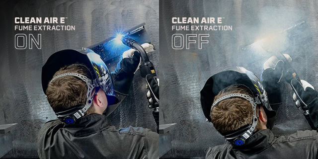

Attacking Weld Fume at the Source
Attacking Weld Fume at the Source

The basics

Benefits of the Bernard® Clean Air™ E Fume Extraction Gun
Maximizing Performance
Proper maintenance and consumable usage
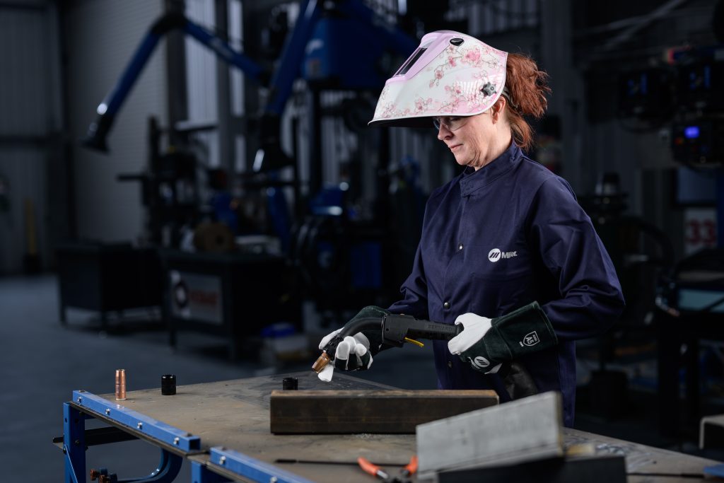
Fume extraction guns can provide results
Learn more about the Bernard® Clean Air E™
Fume Extraction Guns: Understanding the Basics
Fume Extraction Guns: Understanding the Basics
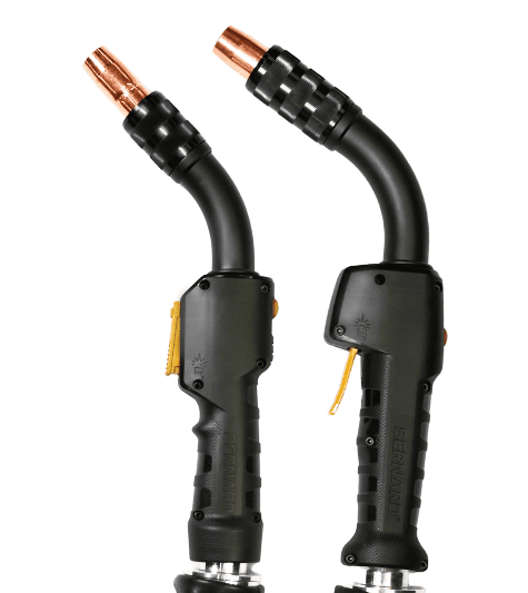
The basics of fume extraction guns

Applications, advantages and limitations
Maintenance tips
How to Prevent 5 Common Welding Gun Failures
How to Prevent 5 Common Welding Gun Failures

Reason No. 1: Exceeding the gun rating
Reason No. 2: Improper setup and grounding

Reason No. 3: Loose connections
Reason No. 4: Damaged power cable

Reason No. 5: Environmental hazards
Additional thoughts on MIG gun failures
Maintenance Tips
From Semi-Automatic to Automatic: Tips for Selecting a Welding Gun

From Semi-Automatic to Automatic: Tips for Selecting a Welding Gun
The Importance of Cutting a Welding Liner Properly
The Importance of Cutting a Welding Gun Liner Properly
The problem with welding gun liners
A new solution for welding gun liners


Tips for Improving MIG Welding
Tips for Improving MIG Welding
revisiting the welding process regularly to ensure its efficiency. Companies should take care to watch for common pitfalls that could negatively affect their progress toward streamlining and improving their operation.Welder training

Assessing the process

Welding gun selection and use
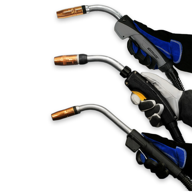
The role of consumables and wire
Keeping on track
Selecting Contact Tips for Robotic Welding
Selecting Contact Tips for Robotic Welding
How do contact tips affect efficiency?

fuse in the fuse box that is your robotic
welding cell. But this small fuse can have
a big impact on productivity.Types of contact tips
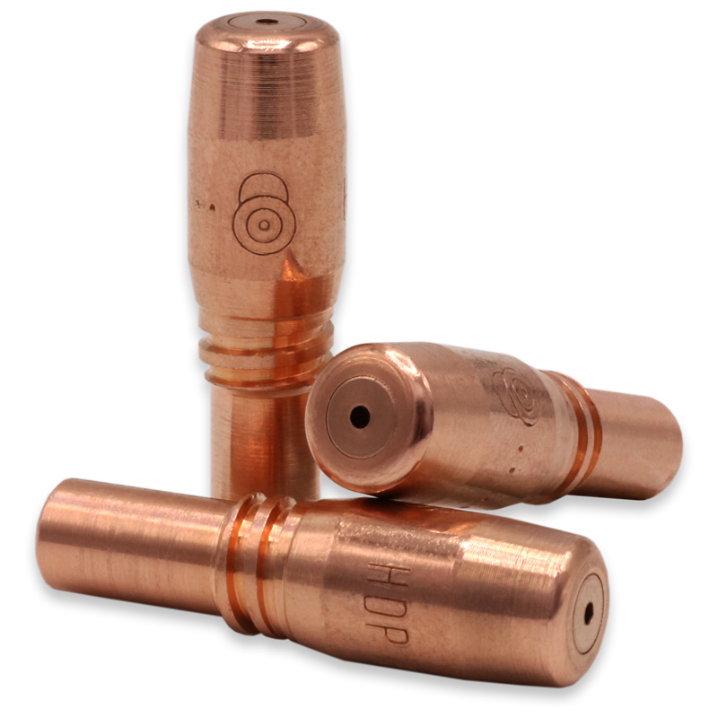
Common pitfalls with contact tips
Analyzing the robotic operation
Optimizing contact tip efficiency in robotic welding
How Robotic Welding Supervisors Can Improve the Operation
How Robotic Welding Supervisors Can Improve the Operation

Find opportunities for improvement
Rely on available resources
• Poor joint configurations, or
• The need for tooling adjustmentsBest Practices for Robotic Welding Supervisors
Best Practices for Robotic Welding Supervisors

• High weld quality
• Cost saving
• Parts consistency
To maximize uptime in a robotic welding system, welding supervisors need to look beyond the administrative and operational duties often involved with this position and consider the actual components in the system. Maintenance personnel can often help.
Keeping an accurate, detailed log of all activities in a robotic welding cell can help welding supervisors maintain control over changes that could impact performance of the robotic welding system. Information to document includes:
• Parts that have been cleaned
• Consumable changes
• Drive roll tension adjustments
• Installation of a new welding wire drumThis article is the first in a two-part series focused on key information welding supervisors should know to help ensure robotic welding success. Read article two, How Robotic Welding Supervisors Can Improve the Operation.
Understanding Fixed Automatic Welding Guns
Understanding Fixed Automatic Welding Guns

About fixed automation welding
Common Factors for Suitable Applications
2. Large parts with very long welds or several similar welds
3. Large parts that would be difficult to weld manuallySetups
Avoiding pitfalls in the process

Looking at the choices
Necks

Cable Lengths
Additional considerations
How to Prevent Common Causes of Poor Welding Wire Feeding
How to Prevent Common Causes of Poor Welding Wire Feeding
What’s happening with the feeder?

Take a look at the drive rolls

is the wrong size for the wire being used.Check the liner

Monitor for contact tip wear
Additional thoughts
AccuLock R Consumables Reduce Downtime in Robotic Welding
AccuLock R Consumables Reduce Downtime in Robotic Welding
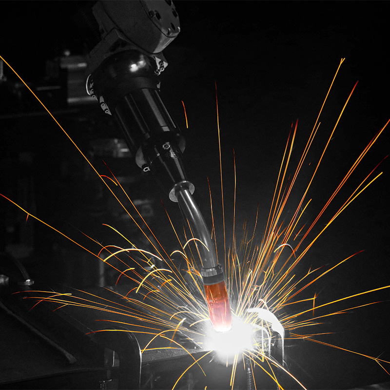
Consumable challenges
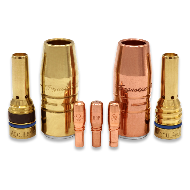
A new consumables solution


Making the change
How to Successfully Implement a Robotic Welding System
How to Successfully Implement a Robotic Welding System
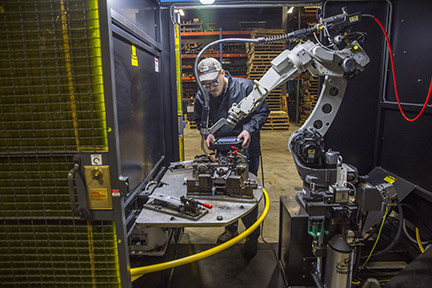
Why robotic welding?
In addition, the national and international marketplace has become increasingly competitive, with companies seeking contracts from any number and any size of business. Investing in welding automation can help set up a company on the path to compete at a global level.Here are additional benefits:
Repeatability is key
Assess the workflow

Robotics or fixed automation?
Consider the available space
Integrators and equipment selection

Employee training
Justifying the expense and calculating payback
Improving Welding Automation Safety With Risk Assessment and Training
Improving Welding Automation Safety With Risk Assessment and Training
Robotic welding safety hazards and resources

External Resources
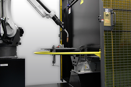
Safe use of robotic welding guns, consumables and reamers
Personal Protective Equipment (PPE)
Navigating the robotic welding cell safely
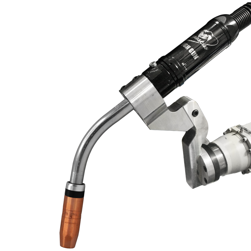
Unenclosed Robotic Systems
Other safety considerations
Creating a culture of safety
![]()