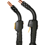
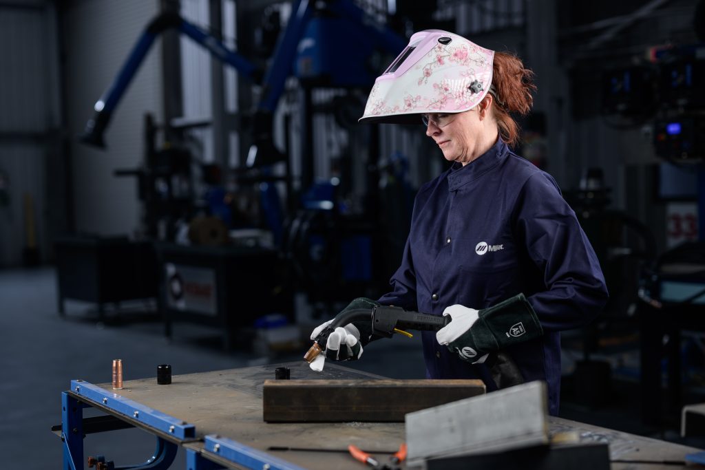
(Re)Introducing the Bernard® S-Gun™ Semi-Automatic Air-Cooled MIG Gun
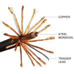
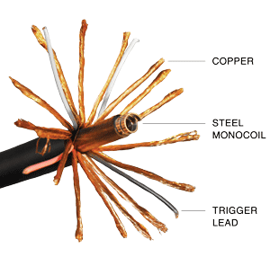
The Bernard® S-Gun™ is back—with refreshed configurations and enhanced flexibility—making it better suited than ever for demanding, hard-to-feed welding applications. While our steel monocoil cable isn’t new, its thoughtful updates make a noticeable difference in performance and reliability.
Why Choose the S-Gun? It Starts with the Cable
The S-Gun sets itself apart with a steel monocoil cable delivers superior structural integrity. This design offers excellent pinch resistance, helping maintain consistent gas flow and reliable wire feedability—even in tough conditions.
This makes the S-Gun ideal for applications that require longer cable lengths frequently looped or routed around tight corners. The result? Fewer pinch-related issues and a smoother welding experience.
Easy Configuration with Our Online Tool
Building an S-Gun to fit your needs is simple:
- Start with your amperage and cable length
- Select your preferred handle, neck, consumables, and power pin
- Generate a customized parts list—delivered right to your or your customer’s inbox
Visit our online configurator. In just a few clicks, you’ll have a tailored MIG gun solution that’s ready for your job. It’s fast, convenient, and eliminates the guesswork.
What’s New in the S-Gun Lineup?
To ensure we continue offering the best tools for the job, we’ve updated the S-Gun lineup with additional configurations and more options:
Model Options
- S250 (NEW)
- S350
- S450
Available in 15 ft., 20 ft., or 25 ft. cable lengths
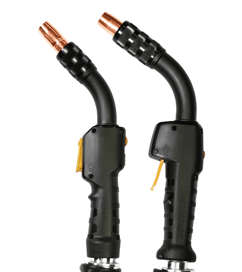
Handle Choices
- Straight T-Series: Standard or locking trigger
- Curved Compact O-Series: Standard trigger only
Consumables
- AccuLock™ S system
- Choose Front Load or Rear Load liner styles
Power Pin Compatibility
- Miller®
- Tweco® #4 (with Lincoln® lead)
- Lincoln®
- Euro-style
These changes allow for more tailored configurations to meet specific application needs while streamlining ordering and setup.
Questions? We’re Here to Help
If you have any questions about the S-Gun or would like help configuring the right setup, our Customer Service team is ready to assist.
- Call us at 855-MIGWELD (644-9353)
- Or email cs@itwmig.com
DISCONTINUED PRODUCT | Clean Air™ Fume Extraction MIG Guns — 300 Amp, 400 Amp Models

DISCONTINUED PRODUCT | Clean Air™ Fume Extraction MIG Guns — 300 Amp, 400 Amp Models
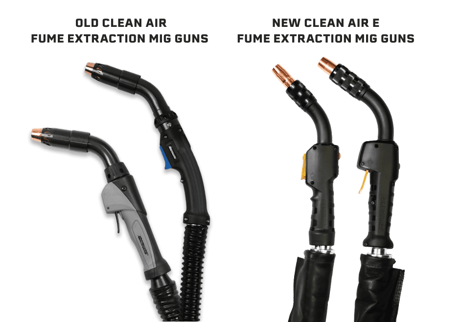
Following the successful launch of Bernard’s Clean Air E™ fume extraction MIG gun on March 20, 2025, Bernard will discontinue its Clean Air fume extraction MIG guns in 300-amp and 400-amp configurations, effective September 30, 2025.
Examples of impacted configurations include:
CL30XXXXXXXX
CL40XXXXXXXX
Customers using these models are encouraged to transition to the next-generation Clean Air E fume extraction MIG gun. Clean Air E is an upgrade in performance. Designed for enhanced comfort, durability, and reduced welder fatigue, Clean Air E delivers efficient extraction with up to 95% fume capture with improved weld visibility while still enduring in the toughest welding environments.
If you have any questions, please contact Customer Service by phone 855.MIGWLED (644.9353) or by email cs@itwmig.com.
DISCONTINUED PRODUCT | Quik Tip™ Flush Diffuser, D1FQ
DISCONTINUED PRODUCT | Quik Tip™ Flush Diffuser, D1FQ
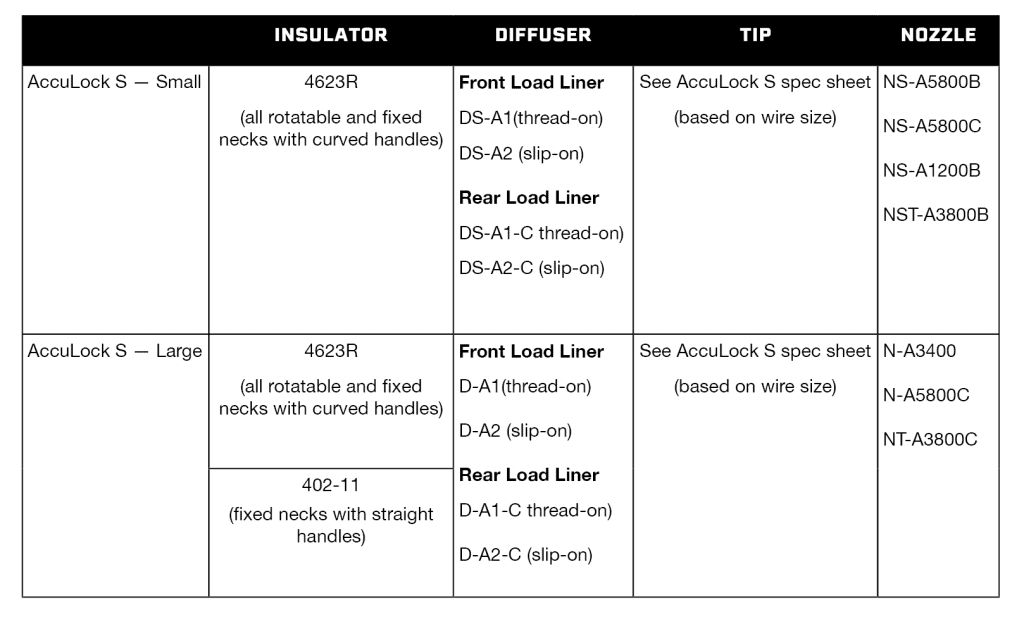
Effective August 22, 2025, Bernard will discontinue Quik Tip flush diffuser, D1FQ. There is no direct replacement; however, you can choose to install Quik Tip diffuser D118Q (1/8” recess) or convert to AccuLock S with a flush nozzle.
To convert from Quik Tip to AccuLock S, the following consumables are needed:
If you have any questions, please contact Customer Service by phone 855.MIGWLED (644.9353) or by email cs@itwmig.com.
DISCONTINUED PRODUCT | 1780006, Semi-Automatic Air-Cooled Handle Kit
DISCONTINUED PRODUCT | 1780006, Semi-Automatic Air-Cooled Handle Kit
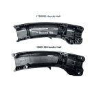
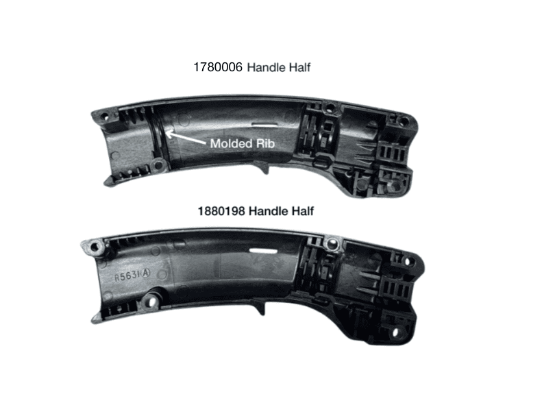
Effective August 22, 2025, Bernard will discontinue handle kit 1780006. Handle kit 1880198 can be ordered as a direct replacement, which includes handle halves, screws and posts. This handle also requires a spring strain relief, part number 2520042, to be installed at the base of the handle, enclosed between the handle halves.
Handle kit 1780086 was originally used as the large B Series handle (yellow trigger) for our 400amp semi-automatic air-cooled MIG gun but has not been the factory installed handle since 2014. This handle style does not accept a spring strain relief. Rather, the inner halves contained a molded “rib”, shown below, to close around the cable jacket and prevent debris from entering the handle through the bottom. The spring strain relief required for replacement handle kit 1880198 serves this function.
PRODUCT UPDATE | New Power Pin Option for IronPro™ Series FCAW Guns
PRODUCT UPDATE | New Power Pin Option for IronPro™ Series FCAW Guns
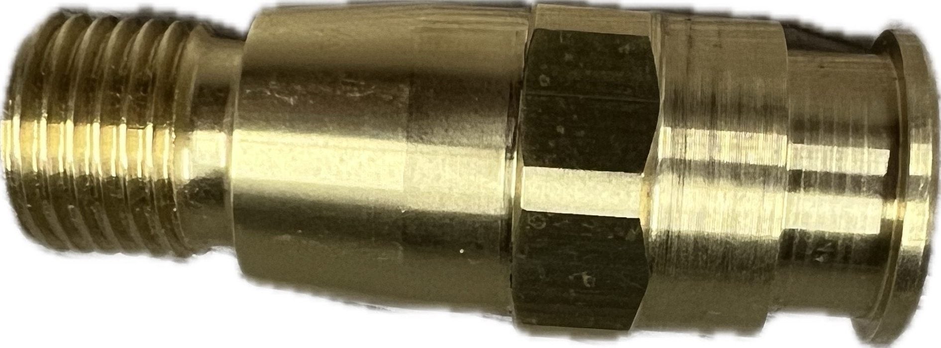
We have expanded the power pin options available for our IronPro™ Series FCAW Guns. Power pin 2200363 (pictured below) is specifically designed for use in self-shielded flux-cored applications on a wide range of Lincoln® LN-25® feeder models.
You may order the following IronPro 350 FCAW Guns with this power pin:
| 10 ft. | 15 ft. |
|---|---|
| GL3510MLNZ | GL3515MLNZ |
| GL3510MSXZ | GL3515MSXZ |
If you have any questions, please call or email our Customer Service team at 855.644.9353 (MIGWELD) or cs@itwmig.com.
PRODUCT UPDATE: S-Gun™ Simplification – Discontinued Configuration Selections
PRODUCT UPDATE: S-Gun™ Simplification – Discontinued Configuration Selections
Continuing the simplification efforts for our S-Gun™ Semi-Automatic Air-Cooled MIG Guns, effective June 27, 2025, all S-Guns in 500 amp, 600amp or 10’ configurations in any amperage will be discontinued.
Examples of configurations that will be discontinued:
- S50XXXXXXXX
- S60XXXXXXXX
- SXX10XXXXXX
For 500 amp or 600 amp S-Guns that are no longer available, we suggest ordering a similar configuration from our BTB Semi-Automatic Air-Cooled MIG Guns.
- S50XXXXXXXX, suggested replacement will be Q50XXXXXXXX
- S60XXXXXXXX, suggested replacement will be Q60XXXXXXXX
For 10’ S-Gun MIG Guns, a similar S-Gun configuration can be ordered in a 15’ length. Or, a BTB configuration in 10’ in the same amperage.
- SXX10XXXXXX, suggested replacement will be SXX15XXXXXX
- SXX10XXXXXX, suggested replacement will be QXX10XXXXXX
If you have any questions, please contact Customer Service by phone 855.MIGWLED (644.9353) or by email cs@itwmig.com.
DISCONTINUED PRODUCT | Elliptical Diffusers
DISCONTINUED PRODUCT | Elliptical Conversion Diffusers
Effective June 20th, 2025, the following Elliptical series diffusers will be discontinued from our product offering:
| Part Number |
|---|
| 4235T |
| 4335T |
| 4435T |
| 4635T |
| 4635T-116 |
These diffusers allowed Elliptical series consumables to be compatible with Tweco® and Tregaskiss® style MIG guns. While there are no direct replacements for these parts, we suggest converting to AccuLock™ S consumables. For Tweco® style MIG guns, AccuLock™ S consumables can be installed by using adaptor 1380030. No adaptor is needed for Tregaskiss® MIG guns.
For an easy change-over, we offer AccuLock™ S conversion kits complete with a variety of tips, nozzles, diffusers and Tweco® adaptor. Kit Part Number: ALCSK-1
If you have any questions, please contact Customer Service by phone 855.MIGWLED (644.9353) or by email cs@itwmig.com.
PRODUCT UPDATE — Configurator Simplification, BTB Semi-Automatic MIG Gun

PRODUCT UPDATE – Configurator Simplification,
BTB Semi-Automatic MIG Gun
Effective April 22, 2025, we have simplified our BTB MIG Gun configurator selections. Check out your Best of The Best MIG Gun options below:
- Cable: Available in 200, 300, 400, 500 or 600 amps from 10, 15, 20 to 25 ft (no changes)
- Handles: Chose from B Series (small, large), O Series (small), or T Series (small, large)
- Consumables: Configurable with AccuLock™ S for Front Load or Rear Load liners, or Centerfire™ with Rear Load liners
- Power Pin: Available options include Miller®, Lincoln®, Euro Or Tweco® #4
BTB MIG Gun configurations that include options not listed above will still remain available for purchase. Our Reverse Lookup tool can help provide a parts breakdown for ordering information.
If you have any questions or would like more information, please contact Customer Service by phone at 1.855.MIGWELD (644.9353) or email at cs@itwmig.com.
Mastering MIG welding with adjustments, equipment and techniques

Mastering MIG welding with adjustments, equipment and techniques
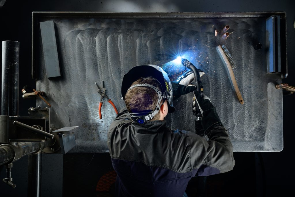
Discover essential adjustments, equipment tips, and expert techniques to accelerate your MIG welding game by reading our article in the October issue of The Welder. You’ll learn how to balance voltage and wire feed speed for flawless welds, select the right welder and shielding gas, and master gun angle and travel speed. Plus, we’ll guide you through troubleshooting common challenges to ensure consistent, high-quality results. Don’t miss out on transforming your welding skills—dive into the full article now!
Attacking Weld Fume at the Source

Attacking Weld Fume at the Source
The Occupational Safety and Health Administration (OSHA) and other safety regulatory bodies set the allowable exposure limits for weld fumes and other particulates, including hexavalent chromium, with the aim of protecting employees against potential health hazards in the workplace. Providing welding operators with proper ventilation during the welding process is an important step companies can take to help meet the standards — and to help provide a safe and comfortable work environment.

Companies may opt to invest in centralized fume extraction systems, which are designed to protect the entire shop area. These systems involve the installation of new ductwork and fans to remove fumes and are highly effective, but they are also more expensive than other options. A viable alternative for some companies is a fume extraction gun used in conjunction with a fume extraction device or localized filtration system.
Fume extraction guns are available in a variety of amperages (typically 300 to 600), cable styles and handle designs. As with any welding equipment, they have their best applications, advantages and limitations, as well as recommended techniques for achieving the best results.
The basics
Fume extraction guns operate by capturing the fume generated by the welding process right at the source, over and around the weld pool. The weld fumes removed by these guns are composed of a combination of the filler metal and base material.
Various manufacturers have proprietary means of constructing guns to conduct this action, but at a basic level they all operate similarly: by mass flow, or the movement of material. A vacuum chamber suctions the fumes through the handle of the gun, into the gun’s hose and through to a port on the filtration system (sometimes informally referred to as a vacuum box).

Typically, fume extraction guns are larger than regular welding guns, and include the vacuum and hose that are necessary to extract the fumes. Some manufacturers offer fume extraction guns with a vacuum hose swivel on the rear of the handle to make them easier to maneuver. Also, design advancements have minimized the handle weight and size to make the guns as light as possible for operator comfort, while still offering consistent fume extraction benefits.
Benefits of the Bernard® Clean Air™ E Fume Extraction Gun
The Bernard® Clean Air E™ fume extraction gun is designed to efficiently capture welding fumes at the source, helping to create a cleaner work environment. This gun is particularly well-suited for applications using solid welding wire and for operations in confined spaces, where fume extraction directly in the welding operator’s breathing zone is essential.
Industries that frequently benefit from this technology include shipbuilding, heavy equipment manufacturing, and general fabrication, especially when working with mild or carbon steel. Additionally, for applications in petrochemical industries or those involving stainless steel welding, where higher levels of hexavalent chromium are present, the Clean Air E™ gun provides an effective solution for improving air quality.
Designed for high-amperage and high-deposition rate applications, this gun performs best in flat and horizontal welding positions, where it can effectively capture rising fume particles. While fume extraction in out-of-position welding can be more challenging due to the natural rise of fumes, proper technique and positioning can help maximize effectiveness.
Maximizing Performance
The Clean Air E™ fume extraction gun operates similarly to a standard MIG gun, making it easy for welding operators to adapt to. To achieve the best results, consider these best practices:
- Optimize Extraction Settings – Adjust the vacuum system like the Miller FILTAIR® 215 to balance fume capture without affecting shielding gas coverage.
- Maintain Proper Gun Positioning – Keep the gun at the recommended angle to ensure optimal fume collection.
- Perform Regular Maintenance – Clean the extraction system and gun components to maintain consistent performance.
By integrating the Bernard® Clean Air™ E fume extraction gun into your welding operations, you can enhance fume control while maintaining welding quality and efficiency. Fume extraction guns operate by capturing the fume generated by the welding process right at the source, over and around the weld pool. As with any piece of welding equipment, fume extraction guns benefit from preventive maintenance.
Flux-cored wire allows vacuum adjustment
Because flux-cored wire produces a slag, it generates more weld fume. However, one benefit of using self-shielded flux-cored wire, for example, is it allows the ability to increase the vacuum level of the gun. Welding operators can close off all the vents and utilize the long shroud. This action maximizes the vacuum at the front end of the gun without concern for disturbing the shielding gas, since there is none generates with self-shielded flux-cored wire. When using gas-shielded flux-cored wire, a 0 to 15-degree angle will help maximize fume collection.
Pause at the end
At the end of the weld, welding operators can pause for 10 to 15 seconds, holding the fume extraction gun in place without depositing weld metal. This action allows the gun to capture residual fumes as the weld bead is cooling.
Wire type determines stickout
The contact tip to work distance can be longer — about 1/2 inch to 3/4 inch — when welding with flux-cored wire and a fume extraction gun. With solid wire, welding operators should try to keep the stickout to 1/2 inch or less to maximize fume capture. These lengths are comparable to the stickout lengths used with standard MIG guns.
Experiment with the air control regulator
Some guns, like the Clean Air E™, incorporate a slider or toggle mechanism conveniently located on the gun handle, while others integrate this function internally.
This adjustability is essential for balancing fume extraction with shielding gas coverage. Too much suction can disrupt the protective gas flow, leading to weld defects like porosity, while too little may not effectively capture harmful fumes. By using the built-in adjustment feature, operators can increase or decrease suction as needed to maintain optimal fume control while ensuring proper weld protection.
Finding the right balance may require some trial and error. To optimize performance, welding operators should test the air control setting on scrap material before welding on a final product. This ensures that fume extraction is maximized without negatively affecting weld quality.
With the Clean Air E™ and other adjustable fume extraction guns, operators have greater control over their work environment—helping to improve air quality while maintaining welding efficiency.
Proper maintenance and consumable usage
As with any piece of welding equipment, fume extraction guns benefit from preventive maintenance. Caring for them is similar to caring for a standard MIG gun. Also note that using flux-cored wire with these guns requires more frequent gun maintenance than solid wire because of the slag and fumes it generates. Regular maintenance is important to help prevent a clog or spatter buildup, which can limit the fume capture rate.
Inspecting and maintaining the front end of the gun is key to optimizing fume extraction. Frequently inspect the nozzle and contact tip for signs of spatter buildup, which along with blocking the fume extraction can also obstruct shielding gas flow and cause weld defects. Spatter buildup also can cause consumables to fail prematurely. Replace the consumables if spatter buildup appears, or clean them according to the manufacturer’s recommendations.
Also, inspect the vacuum hose regularly for damage such as cuts or kinks, which can lead to loss of suction. Replace a damaged vacuum hose as necessary.
Regarding consumables, using the manufacturer’s recommended consumables package with a fume extraction gun helps optimize performance, as the guns are engineered to get the best results with specific consumables.
When in doubt about maintenance or any other aspect of using a fume extraction gun, consider working with a trusted welding distributor, certified industrial hygienist and/or the gun manufacturer to address any questions or concerns.
Fume extraction guns can provide results
In combination with many other variables in the welding operation — wire selection, specific transfer methods and welding processes, welding operator technique, and base material selection — fume extraction guns can help companies maintain compliance with safety regulations and create a cleaner, more comfortable welding environment. Proper use and maintenance of the equipment is important to get optimal results.
Learn more about the Bernard® Clean Air E™
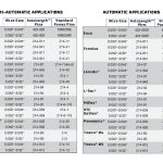
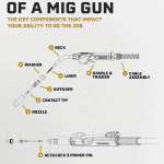
New industry standards from the Occupational Safety and Health Administration (OSHA) are protecting employees against potential health hazards in the workplace. These regulations, which dictate allowable exposure limits of welding fumes and other particulates (including hexavalent chromium), have led many companies to invest in fume extraction equipment. An increased desire to maintain optimal welding operator safety and to attract new skilled welding operators to the field is also a consideration in investing in this equipment — companies want to create the most comfortable and healthy work environment possible. The Clean Air E™ MIG fume extraction gun, as shown here, operates by capturing the fume generated by the welding process right at the source, over and around the weld pool. With interchangeable shroud options to help customize your extraction for your application. Some companies may opt for centralized fume extraction systems, which are designed to protect the entire shop area. These systems involve the installation of new ductwork and can be a costly investment for capturing fume particulate in the air. Fume extraction guns are available in a variety of amperages, cable styles and handle designs. As with any welding equipment, they have their advantages and limitations, best applications, maintenance requirements and more. In combination with many other variables in the welding operation; welding wire selection, specific transfer methods and welding processes, welding operator behavior and base material selection — fume extraction guns can help companies maintain compliance with safety regulations and create a cleaner, more comfortable welding environment. Fume extraction guns operate by capturing the fume generated by the welding process right at the source, over and around the weld pool. Various manufacturers have proprietary means of constructing guns to conduct this action, but at a basic level they all operate similarly: by mass flow, or the movement of material. This movement occurs by way of a vacuum chamber that suctions the fumes through the handle of the gun, into the gun’s hose through to a port on the filtration system (sometimes informally referred to as a vacuum box) like the Miller FILTAIR® 215 High-Vacuum Fume Extractor. The welding fumes that these guns remove are composed of a combination of the filler metal and base material. Some fume extraction guns feature adjustable extraction control regulators at the front of the gun handle, which allow welding operators to increase suction as needed (without affecting shielding gas coverage), while others provide this function internally. Regardless of the manner, the ability to balance between the downward flow of shielding gas and the upward flow of the suctioned air is critical. The fume extraction gun needs to provide the appropriate amount of shielding gas to protect the weld from defects such as porosity, without sacrificing the ability to suction fumes efficiently enough to protect the welding operator. The balance allows the weld pool time to react and solidify, and gives the fume particles time to decelerate so they are easier to extract. Typically, fume extraction guns are larger than regular welding guns and tend to be bulky due to the vacuum and hose necessary to extract the fumes. For that reason, some manufacturers create fume extraction guns with a vacuum hose swivel on the rear of the handle to make them easier to maneuver. Manufacturers have also, since fume extraction guns were first introduced (in the late 1960s and early 1970s), found ways to engineer internal components to minimize the handle weight in order to reduce operator fatigue. Fume extraction guns are well-suited for applications using solid welding wire and those in confined spaces. These include, but are not limited to applications in the shipbuilding and heavy equipment manufacturing industries, as well as general manufacturing and fabrication. They are also ideal for welding on stainless steel applications, as this material generates greater levels of hexavalent chromium, and on mild and carbon steel applications. The guns also work well on high amperage and high deposition rate applications and are available, typically, in 300 to 600 amp ranges. Fume extraction guns attach to a localized filtration system, as shown here. Fume removal occurs by way of a vacuum chamber in the fume extraction gun that suctions the fumes through the handle of the gun, into the gun’s hose through to a port on the filtration system. For the best results, fume extraction guns should be used for in-position welding, such as on flat butt welds. In this position, they can most effectively capture fume particles as they rise from the weld pool. In out-of-position welds, the energy of the fume particles causes them to rise at a high rate, making it more difficult for the fume extraction gun to draw them downward and through the vacuum hose. One distinct advantage to fume extraction guns is that they remove the fumes at the source. This will minimize the amount that enters the welding operator’s immediate breathing zone. As with any piece of welding equipment, fume extraction guns benefit from preventive maintenance. Caring for them is similar to caring for a standard GMAW gun. Regularly check for tight connections throughout the length of the fume extraction gun to ensure good electrical flow. Minimizing electrical resistance helps ensure consistent weld quality and prevent premature failure of the front-end consumables — contact tip, nozzle and diffuser. Frequently inspect the nozzle and contact tip for signs of spatter build-up, too, as such build-up can obstruct shielding gas flow and cause weld defects that ultimately will need to be reworked. Spatter build-up can also cause consumables to fail prematurely. Replace the consumables if spatter build-up appears or clean them according to the manufacturer’s recommendation. In some cases the shroud that surrounds the nozzle may also have to be replaced or cleaned free of spatter. To ensure optimal fume extraction capabilities, inspect the vacuum hose regularly for damage, including cuts or kinks that could lead to loss of suction. Replace a damaged vacuum hose as necessary and dispose of it according to the manufacturer’s and/or an industrial hygienist’s directions. Visually inspect the handle for cracks or missing screws, and also check that the gun’s trigger is not sticking or otherwise malfunctioning. Replace or repair these components as necessary. Finally, maintenance on the liner is also important. As with the vacuum hose, use compressed air to clear out any potential blockages during welding wire changeovers or when removing the wire from the gun. Spending an extra few minutes clearing out any debris from the liner can save considerably more time than troubleshooting the weld defects and equipment problems that can result from blockages. Also, track the amount of time that it takes for a liner to wear during the course of the welding operation. Replace the liner prior to that in the future to prevent downtime for replacement during shifts or problems with wire feeding or quality. When in doubt about maintenance or any other aspect of using a fume extraction gun, consider working with a trusted welding distributor, certified industrial hygienist and/or the fume extraction gun manufacturer to address any questions or concerns. Proper use of this equipment can help provide optimal results, and improve the safety and comfort of the welding environment. Our Bernard® BTB and TGX™ MIG Gun boxes are undergoing a packaging change with a fresh new look. While the exterior is changing, the MIG guns inside remain the same — delivering the trusted performance and reliability you depend on. Please be advised you may notice both old and new packaging during the rollout as this change will happen gradually. Effective February 19, 2025, Rear Load liners L3B-10 and L4B-10 are discontinued. Rear Load liners L3B-15 and L4B-15 directly replace L3B-10 and L4B-10, respectively. These replacements are 15ft (4.57 m) in length. For questions, please contact Customer Service by phone at 1.855.MIGWELD (644.9353) or email at cs@itwmig.com. We have expanded the nozzle options available in our AccuLock™ S and Tregaskiss® product families. For AccuLock™ S, we have added the following nozzle options: * For use with Miller Electric HD (High-Deposition) MIG CV GMAW process. For Tregaskiss®, we have added the following nozzle option: * For use with Miller Electric HD (High-Deposition) MIG CV GMAW process. If you have any questions, please call or email our Customer Service team at 855.MIGWELD (644.9353) or cs@itwmig.com. As part of our on-going simplification efforts, we are renaming our current selection of MIG gun liners. This change is effective now, as you will see our literature and website content being updated to reflect the simplified naming structure. We offer four different liner types between our semi-automatic and automation MIG guns. The chart below will show the previous liner name/reference as well as the updated liner name/reference. It’s important to note that the liners themselves are not changing. We will continue to deliver the same premium quality liners, using the same part numbers as we currently do. If you have any questions, please call or email our Customer Service team at 855.644.9353 (MIGWELD) or cs@itwmig.com. Due to low demand, effective February 7, 2025, Tregaskiss will discontinue TOUGH LOCK standard duty gas diffuser 404-25. TOUGH LOCK standard duty gas diffuser 404-10-25 directly replaces 404-25.This replacement is compatible with tapered, standard duty contact tips (403-2-XX, where XX represents wire size). Diffuser 404-10-25 includes a set screw, as shown in the image below. No adjustments will need to be made to the set screw before or after installation. Previously, 404-25 did not have a set screw. For questions, please contact Customer Service by phone at 1.855.MIGWELD (644.9353) or email at cs@itwmig.com. Due to low demand, effective January 17, 2025, the following jacketed liners will be discontinued: There is no suggested replacement for these items. These jacketed liners were previously used in semi-automatic applications but are no longer compatible with our current MIG gun offerings. For questions, please contact Customer Service by phone at 1.855.MIGWELD (644.9353) or email at cs@itwmig.com. To continue to provide the best products and solutions to our customers, we routinely review, assess and evaluate our product line-up to ensure their features and benefits still hold their value. Accordingly, we have decided to discontinue our AutoLength™ power pins, effective January 10, 2025. These AutoLength pins are currently used across both semi-automatic and robotic/fixed automatic product lines. Until the effective date, you can still purchase existing configurations as well as replacement AutoLength pins (or until inventory is depleted, whichever occurs first). The charts below show the standard power pin that replaces each AutoLength option for both welding applications. You may also find instructions here for replacing an AutoLength power pin with a standard power pin. To configure a new MIG gun part number using a standard power pin, please utilize our online configurators. Your new configuration will also include a full parts list. If you have any questions or need assistance configuring a new gun or finding a replacement part number, please contact our Customer Service Team by phone at 1.855.MIGWELD (1.855.644.9353) or via email at CS@itwmig.com. Effective October 11, 2024, the following 100-pack diffusers will be packaged in boxes instead of bags. The box dimensions are 6” x 6” x 4” (15.24cm x 15.24cm x 10.16cm). Due to low demand, effective December 13, 2024, the following QUICK LOAD liners will be discontinued: As a suggested replacement, we offer conventional liners (rear loading). These liners are currently used across both semi-automatic and robotic/fixed automatic product lines. On the effective date, these seven QUICK LOAD liners will no longer be available, removed from our product configurators, and guns previously configured with these liners will no longer be available for purchase. Effective January 1, 2025, all Tregaskiss® BA1 cobot air-cooled MIG guns will be discontinued and replaced with TOUGH GUN® CA3 robotic air-cooled MIG guns. The change supports our commitment to maximize efficiencies and focus on delivering our best quality solutions to our customers. Please contact your ITW sales representative with questions. Effective January 1, 2025, as part of our ongoing commitment to focus on opportunities to innovate our product portfolio and continue delivering sustainable value to our customers, we will be making a change to the unicable used on our TOUGH GUN® CA3 robotic air-cooled MIG guns. The new unicable provides better flexibility in cobot and conventional over-the-arm robotic welding applications. It is important to note the amperage rating of the TOUGH GUN® CA3 MIG gun will change from 385-amp to 350-amp with mixed gases at 100% duty cycle (ratings are based on tests that comply with IEC 60974-7 standards). There will be no change to configured TOUGH GUN® CA3 MIG gun part numbers or its replacement or service parts. If you have any questions about this initiative, please contact your ITW sales representative. We are pleased to announce the launch of our new reamer shroud and wire cutter shroud. These new shrouds are intended to encourage safe practices when the TOUGH GUN® TT4 reamers are used in cobot welding applications where the operator could be near the reamer during operation. Moving forward, all TOUGH GUN® TT4A and TT4E reamers configured specifically for use in cobot welding applications will come factory-equipped with a reamer shroud, and if the reamer is configured with the wire cutter option, the wire cutter shroud will also be factory installed. The wire cutter can be purchased with or without the wire cutter shroud, and the reamer and the wire cutter shrouds are both available for purchase separately for customers who would like to retrofit their existing equipment, but it is important to note that if retrofitting a reamer and/or a wire cutter manufactured before March 2024, additional components will be required. Please contact our technical support team or your local ITW representative for additional assistance if trying to retrofit older models. TT4-SHR WC-400C WC-400-SHR If you have further questions or would like more information, please contact your local ITW representative. MIG welding is a common welding process especially useful for beginner and DIY welders due to its easy-to-learn nature, shorter lead times and lower production costs. The versatility of MIG welding allows users to work on a wide range of materials with less stopping and restarting. The process features a continuous consumable wire electrode being fed through a welding gun and into a weld pool. The gun also feeds a shielding gas alongside the wire to protect the weld pool from contaminants. While there are different types of MIG guns that have unique parts (e.g., water-cooled, air-cooled, fume extraction), all MIG guns have some parts in common. Understanding the components of a MIG gun and the process by which it works will help you make decisions on the consumables and gun type you select for your job. Here’s what you need to know. 1. Nozzle 2. Contact Tip 3. Diffuser 4. Liner 5. Neck 6. Handle and Trigger 7. Cable Assembly 8. Insulator 9. Power PinFume Extraction Guns: Understanding the Basics
Fume Extraction Guns: Understanding the Basics
The basics of fume extraction guns

Applications, advantages and limitations

Maintenance tips
PACKAGING UPDATE — New Bernard® BTB and TGX™ MIG Gun Boxes
PACKAGING UPDATE — New Bernard® BTB and TGX™ MIG Gun Boxes

Discontinued Liners: L3B-10, L4B-10
Discontinued Liners: L3B-10, L4B-10
NEW PRODUCT — Expanded AccuLock™ S and Tregaskiss® Nozzle Offering
NEW PRODUCT — Expanded AccuLock™ S and Tregaskiss® Nozzle Offering
Part Number Bore Size Tip Position Material Quantity Compatibility N-A1218C 1/2″ 1/8’’ recess Copper 10 AccuLock™ S – Large N-A1214C 1/2″ 1/4’’ recess Copper 10 AccuLock™ S – Large N-A3412C* 3/4″ 1/2’’ Copper 10 AccuLock™ S – Large Part Number Bore Size Tip Position Material Quantity Compatibility 401-9-75* 3/4″ 1/2″ Copper 10 TOUGH LOCK® Diffuser
404-32 (Robotic)
404-26 (Semi-Automatic)
AccuLock™ R Diffuser
D-ATSH (Slip-On)Update to Liner Descriptions
Update to Liner Descriptions
Previous Liner Name/Reference Updated Liner Name/Reference AccuLock S (Dual Lock) Liner Front Load Liner Conventional Liner Rear Load Liner QUICK LOAD® Pro Liner (Automation Only) E-Z Feed™ Liner QUICK LOAD® (There is no name change for this product) Discontinued: TOUCH LOCK® standard duty gas diffuser, Part Number 404-25
Discontinued: TOUCH LOCK® standard duty gas diffuser, Part Number 404-25

Discontinued Parts: Jacketed Liners, LJ-XXXX-XX
Discontinued Parts: Jacketed Liners, LJ-XXXX-XX
Part Number Description LJ-3545-15 Jacketed liner, 0.035″ – 0.045″, 15′ LJ-3545-25 Jacketed liner, 0.035″ – 0.045″, 25′ LJ-5262-12 Jacketed liner, 0.052″ – 1/16″, 12′ LJ-5262-15 Jacketed liner, 0.052″ – 1/16″, 15′ LJ-5262-25 Jacketed liner, 0.052″ – 1/16″, 25′ Discontinued Products – AutoLength™ Power Pins
Discontinued Products – AutoLength™ Power Pins

PACKAGING CHANGE — Diffusers 404-XX, D-ATSH-100, D-ATTH-100
PACKAGING CHANGE — Diffusers 404-XX,
D-ATSH-100, D-ATTH-100100-pack Diffusers Description 404-18 TOUGH LOCK®, Standard Duty 404-20 TOUGH LOCK, HD 404-26 TOUGH LOCK, HD 404-30 TOUGH LOCK, HD 404-31 TOUGH LOCK, HD 404-32 TOUGH LOCK, HD for Robotic D-ATSH-100 AccuLock™ R Diffuser, Slip-On D-ATTH-100 AccuLock R Diffuser, Thread-On Discontinued Parts: QUICK LOAD® Liners, 415-30-XXQ, 415-564-XXQ, 415-332-XXQ
Discontinued Parts: QUICK LOAD® Liners, 415-30-XXQ, 415-564-XXQ, 415-332-XXQ
QUICK LOAD® Liner Tregaskiss® Conventional Liner
(Robotic/Automation)Bernard® Conventional Liner
(Semi-Auto)415-30-6Q 415-30-25 L2A-15 415-30-15Q 415-30-25 L2A-15 415-564-6Q 415-564-6 L6A-15 415-564-15Q 415-564-15 L6A-15 415-564-25Q 415-564-25 L6A-25 415-332-15Q 415-332-15 L7A-15 415-332-25Q 415-332-25 L7A-25
Please use our online configurators and/or consult Customer Service to find a suitable replacement by phone at 1.855.MIGWELD (644.9353) or email at cs@itwmig.com.DISCONTINUED PRODUCT — BA1 COBOT MIG GUN
DISCONTINUED PRODUCT — BA1 COBOT MIG GUN
Affected Part Numbers Direct Replacements All MIG gun part numbers beginning with BA12 Replace digits “BA12” with “RA12” (the rest of the part number remains the same) All replaceable unicable part numbers beginning with BA1U Replace digits “BA1U” with “CA3U” (the rest of the part number remains the same) All replaceable unicable part numbers beginning with EBA1U Replace digits “EBA1U” with “ECA3U” (the rest of the part number remains the same) PRODUCT UPDATE — CHANGE TO THE CABLE USED ON TOUGH GUN® CA3 MIG GUNS
PRODUCT UPDATE — CHANGE TO THE CABLE USED ON TOUGH GUN® CA3 MIG GUNS
NEW PRODUCT: SHROUDS FOR THE TOUGH GUN® TT4 REAMER AND WIRE CUTTER
NEW PRODUCT: SHROUDS FOR THE TOUGH GUN® TT4 REAMER AND WIRE CUTTER


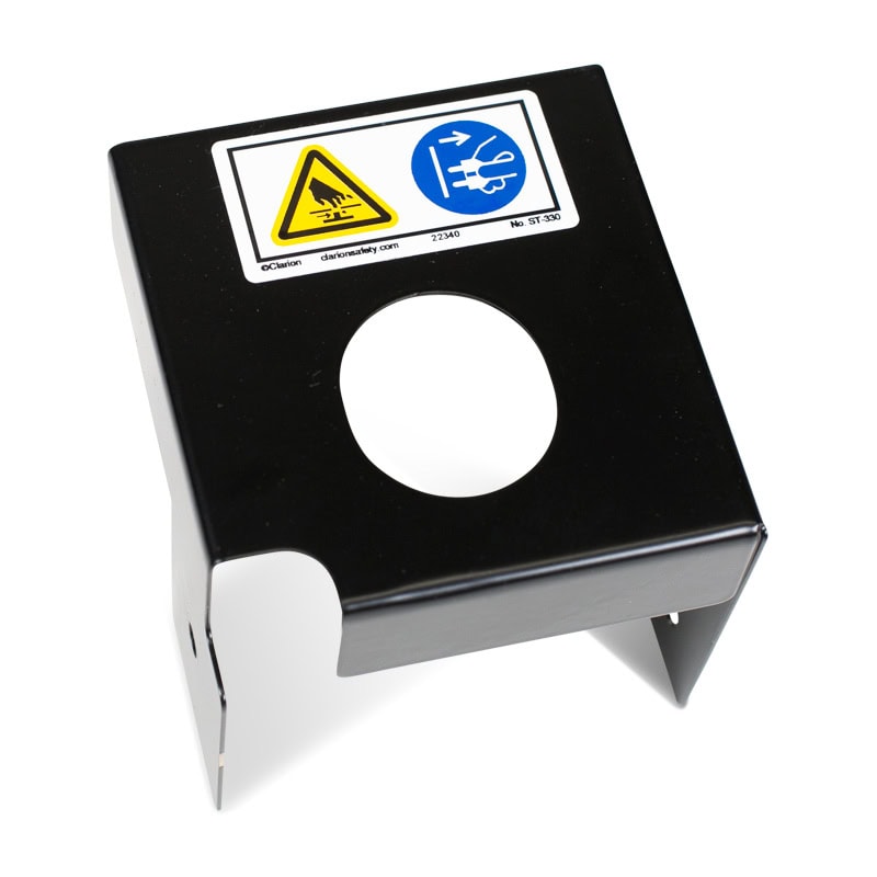
Reamer shroud only, for
TOUGH GUN® TT4 reamer
Wire cutter equipped
with wire cutter shroud
Wire cutter shroud only,
for wire cutterKey MIG Gun Components for Job Performance
Key MIG Gun Components for Job Performance
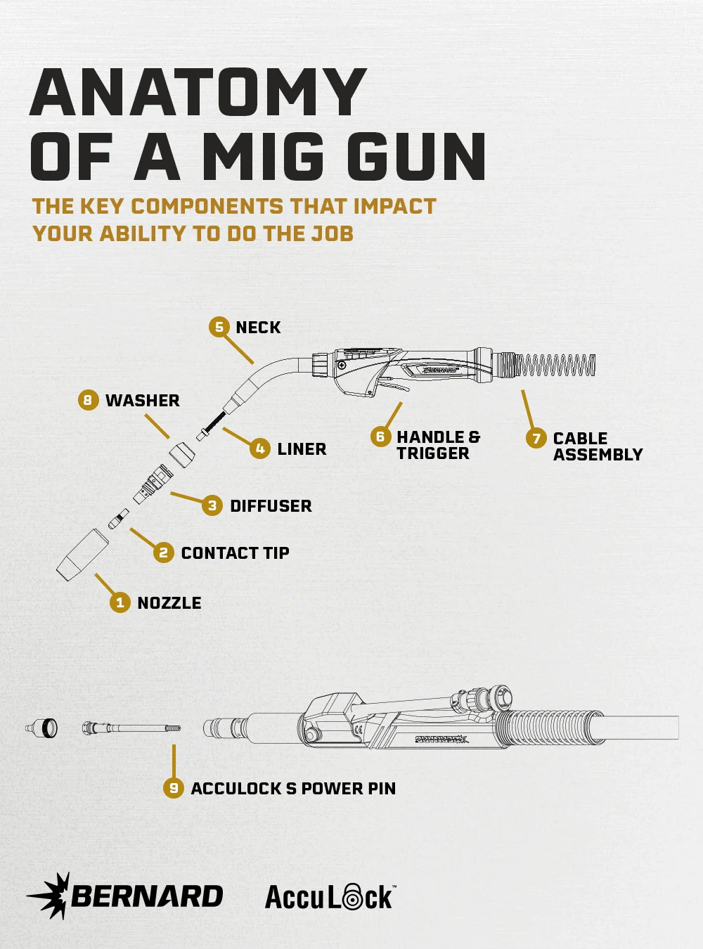
CONSUMABLES
ESSENTIAL GUN COMPONENTS
OTHER COMPONENTS

![]()